
Revision Histories for Versions 11.0.0 - 13.2.0
Shown below are VISRAD revision summaries for:
Version 13.2.0
- A new instance of VISRAD can now be launched by selecting the File | New Window menu item. While this update was primarily made to facilitate opening a second process on Mac platforms, it is also supported on Windows and Linux platforms. To clarify the options in the File menu, the menu item File | New has been changed to File | New Workspace.
- A new workspace can now be loaded into VISRAD by dragging the file from a platform's folder.
- Computational Efficiency:
- Upgrades were made to improved the computational efficiency of the View Factors calculation. For test cases with many surface elements, required CPU times were reduced by factors of ~ 7 to 10.
- Upgrades were made to speed up the rending of laser beams (specifically, finding the intersections of the laser beams with target components). CPU times were reduced by a factor of ~ a few in test cases. Speedups depend on the number of polygons used to render each laser beam cone (see Beam Cone Parameters settings on Laser tab of Preferences).
- Upgrades were made to speed up the clipping algorithms for Target Components being clipped. CPU times were reduced by a factor of ~ a few in test cases.
- Target Components Library: When importing components from the Target Components Library, the folders containing target components in the library can now also be moved along with the folder contents.
- LMJ Target Chamber:
- The Petal laser beam has been added to the LMJ laser system.
- Spatial profiles have been added for:
LMJ Profile |
R-major+ (mm) |
R-minor+ (mm) |
Supergaussian n |
Circular Type D |
470 |
470 |
3.0 |
Circular Type E |
750 |
750 |
4.5 |
Circular Type F |
315 |
315 |
2.0 |
Elliptical Type A |
1500 |
750 |
3.1 |
+ Radii at 3% of Imax .
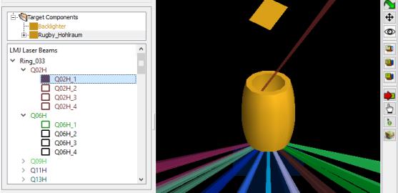
- Laser Beams List: For the LMJ target chamber, beams are now grouped into quads. Setting the properties of a beam quad (e.g., pointing) affects all of the beams in the quad. The properties of individual beams can also be edited.
- Bug fixes:
- Preferences dialog, Simulation tab: When the box is checked to limit the maximum number of threads, the entered value is now correctly utilized.
- Chamber Component Parameters widget: On the Position tab, utilization of the sliders to adjust the Orientation Angles is now implemented correctly.
- Element Parameters widget (used for Multi-Element objects): On the Position tab, utilization of the sliders to adjust the Orientation Angles is now implemented correctly.
- A crash that occurred when attempting to cut and paste values into table cells (e.g., when specifying time-dependent material properties) has been fixed.
Version 13.1.1
- New, more robust activation procedure has been implemented. Activation daemons are no longer required. Affected users will receive new activation codes.
Version 13.1.0
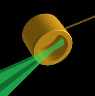
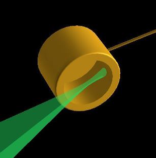
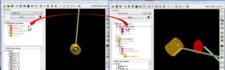
- OMEGA laser system: DPR modeling has been added. When simulating a beam with DPR "on" (i.e., with distributed polarization rotators (DPR) in), the beam is split into two cones, which have a separation of 85 microns at the focal plane. The beam power is split evenly between the two cones. The images below show examples of a beam with DPR on (left) and off (right). Issues related to DPR modeling are:
- DPR modeling can only be turned on for beams that utilize either a Spatial Profile Model that is either Uniform or Custom Supergaussian. In most other cases, the spatial model parameters (i.e., beam spot size, supergaussian exponent) for the various OMEGA DPP's are based on fits to data which had DPR on.
- DPR modeling is not supported for Custom laser beams (including the 4w probe beam), or for laser beams of target chambers other than OMEGA.
- A column indicating DPR status (on/off) has been added to the Laser Beam Summary Table. The DPR status is now included in the exported/imported laser beam data files (CSV and XML).
- A menu item Laser | OMEGA DPR Cones has been added. By default, VISRAD shows both of the DPR cones, but users can specify that only the DPR+ cones or the DPR- cones be displayed.
- OMEGA laser system: phase plate OMEGA SG5 DPP has been added to beam spatial profiles.
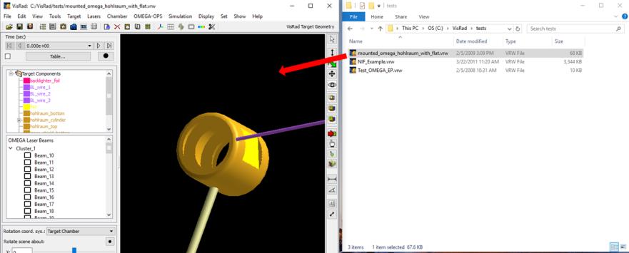
- It is now possible to copy Target Components from one VISRAD application to another by dragging with the mouse. To do this, select one or more items in the Target Components List of one application, and drag them into the Target Components List of the second application (see image below).
- If a folder is selected, the folder with all of its contents is copied.
- Since VISRAD requires unique names for Target Components and unique names for folders of a given parent folder, target component and folder names will automatically be adjusted when name clashes occur (e.g., "Backlighter" will become "Backlighter_2").
- When the reference coordinate system for a Target Component is another Target Component:
- If the reference Target Component is also being copied during the same drag operation, the reference object will remain the same.
- If the reference object is not being copied, the reference coordinate system will be set to the Target Chamber.
- In cases when the Target Chamber is different between the two VISRAD applications (e.g., NIF vs. OMEGA), when the reference coordinate system is a Diagnostic Port or a Target Mount, the reference coordinate system will be set to the Target Chamber.
- Chamber Components:
- CAD files can now be imported directly as Chamber Components. To do this, select the File | Import CAD File | As Chamber Component menu item.
- Custom Chamber Components can now be directly created from Target Components by dragging items from the Target Components List to the Chamber Components List. (Previously, target components had to be added to the Chamber Components Library, and then imported from the library as a Chamber Component.
- Deleting items in the Target Components List or the Chamber Components List can now be done using the "Delete" key.
- Multi-Element objects: Upgrades have been added to checking the values size/grid parameters of Elements when generating Multi-Element objects. Previously, no checks had been made on the size parameters and number of grid points specified by the user, which can be specified either as constants or strings.
- C++ algorithms are now being used for computing view factors and transmission fractions; VISRAD is now entirely in C++. This allows for the possibility of supporting VISRAD apps for tablet platforms at some point in the future.
- Bug fixes:
- Target Positioning Viewer: Fixed problem where Reticles disappeared for large zoom factor in Narrow and Wide OMEGA cameras.
- The tool tip for the Adjust Viewer Angles button on the right side of the Main Graphics Frame has been fixed.
- Setting Preferences,Graphics tab: A problem that occurred on Mac platforms when changing the background color for viewing has been fixed.
- Orientation Angles Calculator. Fixed truncation problem that occurred when utilizing the Copy Angles to Object Parameters button .
Version 13.0.0
- A Subject Index has been added to the Documentation to facilitate locating help on various topics.
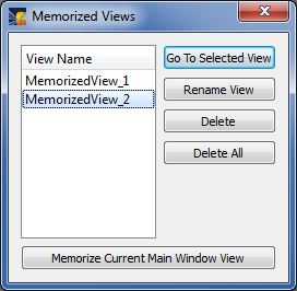
- Memorized Views:
- Memorized Views can now be edited.
- Views corresponding to Diagnostic Port angles can now easily be added to the list of Memorized Views. With this capability, Memorized Views for Diagnostic Ports (e.g., TIMs for the OMEGA chamber) can readily be set up, saved, and edited, and their images exported to files.
- Diagnostic Ports Lists: Dialogs containing a list of Diagnostic Ports have been updated to better support sorting by columns.
- Manipulation of Imported CAD Objects: When importing Target Component data from CAD files, the position of the grid origin in the CAD file relative to the centroid of the object is now saved by VISRAD. This now allows VISRAD to position and orient the object utilizing the CAD object's grid origin. Issues associated with the use of this method include:
- When VISRAD recognizes that valid grid origin data exist for a "GENERALIZED MESH" object (i.e., the object type assigned when reading in a CAD file), an option for Grid Origin is available for the Set Position Of parameter in the Position tab of the Object Parameters Dialog. When this option is selected, the user selects position parameters that correspond to the location of the grid origin.
- The position of the grid origin (relative to the object's centroid) was not saved in previous versions of VISRAD when importing CAD objects. Therefore this approach cannot be used with CAD object data previously read in and stored by VISRAD. The CAD files must be read in again in order to perform manipulations utilizing the grid origin.
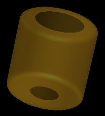
- Target Component properties: Cylindrical Halfraum objects can now have a non-zero radius opening at the bottom. This supports the generation of grids for cylindrical hohlraums with different LEH radii.
- Windows 8 platforms: upgrades were made to improve rendering of Main Window Graphics when exporting or printing images.
- Linux platforms : STEP-formatted CAD files can now be imported on Linux systems.
- Exporting STEP-formatted CAD file data: The ability to export VISRAD Target Component data into STEP-formatted CAD files has been added (currently in "beta" form). All VISRAD Target Component types are supported, but with some limitations, which are noted in the documentation (see Target Components | Importing/Exporting CAD Files).
- Computational efficiency:
- The efficiency of calculating the laser power deposition using AMR (adaptive mesh refinement) grids (Display | Direct Laser Power Deposited | AMR Grid menu item) has been significantly improved.
- Main Window Graphics: the rendering speed for objects containing a large number of surface elements has been significantly improved for cases when the color of surface elements for each object are the same (e.g., when not displaying simulation results).
- Target Positioning Viewer: The rendering of reticles, length and angle measuring tools, and ticks/grid lines was adjusted to avoid obscuration by target components.
- Showing position data of individual Surface Elements:
- On the right side of the Main Window, a new tool button (
 ) has been added which is used to show the position data for Surface Elements picked with the mouse. This data is also available in the Node Positions tab of the Surface Element Parameters Dialog. Utilizing the new tool button eliminates the need to request whether the user wants Power Sources, View Factors, and Radiosities to be updated.
- The size of the nodes displayed for the picked surface/object (using either tool buttons [(), (
 ), or (
 )] or the Point-to-Point Distance Tool) is now set using the value for the Radius of Key Points set on the Graphics tab of Preferences.
- A link to the VISRAD User Forum has been added under the Help menu in the Main Window.
- Port Positions Dialog : Sorting in the Port Positions Table by clicking on column headers has been improved.
- Chamber Ports Viewer:
- Viewing angle (specified using polar and azimuthal angles - q, f), can now be adjusted by either using sliders or entering values and hitter return (Enter) key.
- The efficiency of render text boxes has been improved so that the response of the Chamber Ports Viewer to resizing or mouse movements is significantly improved.
- Right-click menu: the menu items were reorganized to reduce the level of nesting; Hide All and Select All are now always enabled.
- Icons on some buttons in the Set Viewing Parameters dialog were changed to avoid conflicts/confusion with other buttons.
- Target Component Positions Dialog: Additional Key Points have been added for the edge positions of Rectangle and Box objects.
- Target Positioning Viewers:
- Reticle data can now be exported to and imported from CSV-formatted files.
- Individual Reticles can now be applied to a particular view.
- The crosshairs rendered for Reticles can now extended across Target Positioning Views. The option to use extended crosshairs is set in the Graphics tab of Preferences (Use Extended Crosshairs for Reticles check box).
- The Target Positioning Views are now updated when the user enters values in the Rotate and Translate boxes and presses the Return (Enter) key.
- The Target Positioning Views are now updated when clicking on the sliders for Zoom, Rotate, and Translate.
- The Cryo Camera view has been removed from the OMEGA X-TVS/Y-TVS Viewer, as it is obsolete.
- The Smart Camera view for the OMEGA X-TVS/Y-TVS Viewer has been rotated 24.9 degrees to be consistent with the actual camera orientation.
- Clipping Volumes for individual target components can now be disabled. This allows them to be ignored without deleting them. To disable or enable, select one or more Clipping Volumes, right-click, and select Disable or Enable. When disabled, the clipping volume's name is shown in gray in the Target Components List, and it is not rendered in the Main Graphics Window when showing clipping volumes.
- Laser Beams List: A Find menu item has been added. To find a specific beam in the Laser Beams List, right-click anywhere in the list and select Find.
- OMEGA-EP Target Chamber: TIM 15 has been removed from Port EP-31 .
- OMEGA-EP: 2w/4w Probe Beam:
- The reference to "2w" has been dropped, as it is no longer relevant.
- A 4w Stay-Out Zone object can now be added to the grid and displayed. It is a conical object, whose purpose is to evaluate whether target components are in line with the 4w probe beam. To view the 4w Stay-Out Zone, select the Lasers | 4w Probe Beam | Add Stay-out Zone Object. The object is added to the target component grid, and has many of the same features as a normal target component, with the exceptions that the name is not editable, and, by default, it is not included in laser deposition or radiosity calculations.
- A reference to the 4w Stay-Out Zone is also displayed below the 4w Probe Beam in the Laser Beams List. The stay-out zone can be shown/hidden by right-clicking on the item. If selecting Show and the stay-out zone is not in the Target Components List, it is added to the list.
- 4w Probe Beam: The name and several of its parameters are now not editable. When reading in old workspace containing 4w probe beam, parameters for Pointing and f# are automatically reset to recommended values. The user is notified if the parameters are being reset.
- Generating output files containing the time- and wavelength-dependent incident fluxes on individual surface elements (see Multi-Timestep Simulations | Configuring Simulation Parameters in documentation):
- Support has been added to also supply angle-dependent values for the incident intensity on individual surface elements. This supports performing radiation-hydrodynamics calculations in which an angle-, time-, and frequency-dependent external radiation field is applied. (The HELIOS radiation-hydrodynamics code has been updated to utilize the updated VISRAD output files.)
- Warning messages: When exiting VISRAD, a prompt to save the workspace file is not displayed when specified in Preferences (see Edit | Preferences, Warnings tab, "When exiting, prompt to save workspace file" check box). Turning off this prompt has been extended to cases of opening new workspaces without exiting VISRAD.
- Showing Ticks/Gridlines in the Main Graphics Window: The widget used to set tick mark and gridline properties in the Main Graphics Frame (menu item Set | Ruler Properties) now enables/disables widgets based on the check boxes in the upper portion of the widget. This more clearly indicates when ticks and gridlines are shown.
- Multi-Element Target Components: When adding a Polygon element that is regular, the default values for the polygon height and length are the same as those as a normal target component Polygon.
- Point-to-Point Distance Tool: Value of unit normal vector added.
- Bug fixes:
- Chamber Components Dialog: The Viewing tab widget is now visible. A bug hiding it (instead of the Materials tab) was introduced in Ver. 12.1.0.
- Beam. Spot Overlay labels: When regenerating labels, all text box properties are now reinitialized (including Background).
- Multi-Element Objects: A bug occurring when utilizing a Surface of Revolution as a Multi-Element Object has been fixed.
- Select Clipping Volume Type Dialog: When selecting a Clipping Volume type that is a Target Component, the list of available Target Components is now updated correctly.
- A rendering problem that occurred for OMEGA-EP (square) beams when using a large number of points in the z-direction (i.e., axial direction) has been fixed.
- Object Parameters Dialog: On the Positions tab, changing Orientation Angles by clicking with the mouse on the sliders has been fixed.
- Chamber Component Parameters Dialog: Crash occurring when editing Chamber Component parameters has been fixed.
- Chamber Components List: Crash occurring when selecting the Set Viewing Parameters menu item (right-click menu) has been fixed
- Port Positions Table: When displaying port positions using the coordinate system of a specified Laser Beam port, the transformation matrices for that laser beam port are now updated even if the Laser Beam does not have its power On.
- Laser Beam Parameters Dialog: When displaying/editing NIF be parameters, the Port Index on the Properties tab is now displayed correctly.
- Several dialogs which show lists of Diagnostic Ports are now updated appropriately when loading a new workspace which utilizes a different target chamber.
- Crash that sometimes occurred after computing radiosities, then modifying power sources and selecting Regenerate Grid, and then re-computing radiosities has been fixed.
- Clipping Volumes : A bug occurring when duplicating multiple clipping volumes has been fixed.
- Object Parameters Dialog: When automatically updating positions and orientation angles when changing a Target Components's coordinate system parameters, a problem associated with changing the coordinate system parameters multiple times prior to hitting OK or Apply has been fixed.
Version 12.2.0
- Target Positioning Viewers: Support has been added to export all views to image files with one operation. To do this, select the File | Export All menu item in the Target Positioning Viewer. The user then specifies the image size (which is applied to all images), and the base file name. Each view name is then applied to base file name (e.g., for a base name of "test", the OMEGA TVS view file names are "test_X-TVS.jpg" and "test_Y-TVS.jpg").
- The treatment of Memorized Views has been updated.
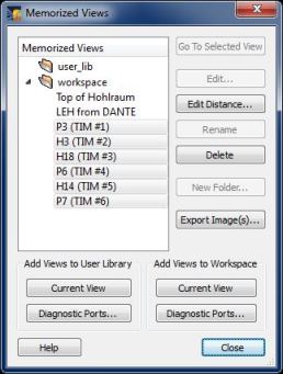
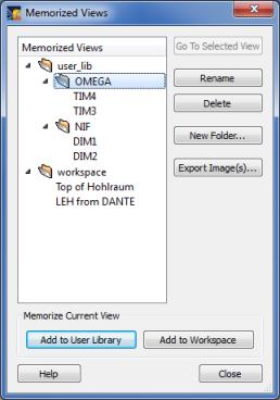
- Memorized Views can now be organized into folders, and reside within one of two top-level folders: "user_lib" and "workspace". Memorized Views residing in the "user_lib" folder are saved to the Preferences File of a user, and therefore are available for all VISRAD workspaces read in by the user. Memorized Views residing in the "workspace" folder are saved to the workspace file the user is currently working on, and therefore are not available to other workspaces.
- Multiple Memorized Views can now be exported to image files with one operation. To do this, select one or more items in the Memorized Views List, and press the Export Images button. The user then specifies the image size (which is applied to all images), and the base file name. Each view name is then applied to base file name (e.g., for a base name of "test", the "TIM3" and "TIM4" view file names are "test_TIM3.jpg" and "test_TIM4.jpg").
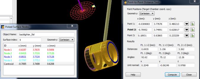
- A tool for conveniently computing the distances between points in 3-D space has been added. The Point-to-Point Distance Tool allows users to select up to 3 points and compute the distances and angles between them. Point positions can be specified using one of the following approaches:
- Entering position data in the boxes
- Hitting the (
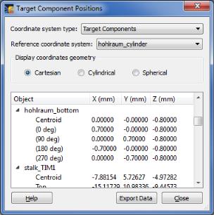
 ) button, and selecting one of the Key Points in the Target Component Positions Dialog
- Hitting the (
 ) button, and picking a surface element in the Main Graphics Window with the mouse.
Once points are selected, hit the Update button to compute relevant distances and angles. If two points are selected, only the distance between those two points is computed. If three points are selected, the distances between each pair of points, and the angles between the 3 points, which define a triangle, are computed.
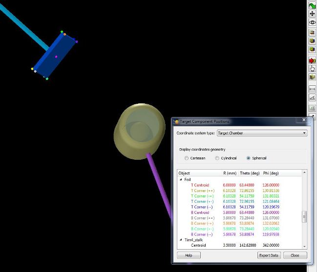
When hitting the () button, the Target Component Positions Dialog is displayed (below left). Double-click on one of the points to automatically populate the position boxes in the Point-to-Point Distance Tool.
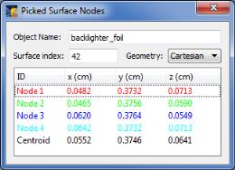
When hitting the () button, that icon appears when moving the mouse in the Main Graphics Window. Pick on a surface element, and a widget showing the node positions and centroid position for that surface element is displayed (below right). The colors correspond to those shown for the nodes of the picked surface element in the Main Graphics Window. Double-click on one of the points in the Picked Surface Nodes widget to automatically populate the position boxes in the Point-to-Point Distance Tool.
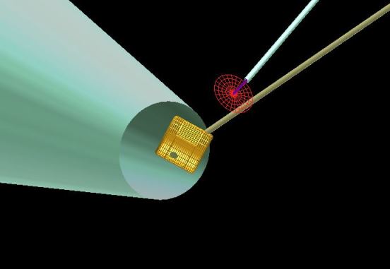
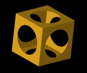
- Two additional Clipping Volume types have been added. It is now possible to clip Target Components with Cones and Spheres (in addition to Cylinders and Boxes). The image below shows an example of a cubical Target Component clipped by a spherical Clipping Volume.
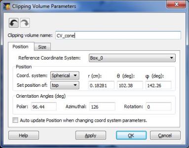
- Clipping Volume Parameters Dialog:
- When clipping by an existing Target Component, the default Reference Coordinate System is the coordinate system of that Target Component, and a coordinate system transformation is performed so that the Clipping Volume is at the same location as the Target Component.
- Support for Undo/Redo has been added.
- The option to automatically update the position and angle values when changing the Reference Coordinate System has been added.
- The Rotation angle value can now be set up the user.
- In the Spatial Profile tab of the Laser Beam Parameters dialog, the OMEGA SG8-Flat DPP has been added to the list of available spatial profile models. The SG8-Flat DPPs have a profile with R(1/e) = 438 mm and supergaussian index of n = 5.8.
- Bug fixes:
- A problem causing a crash with opening a workspace containing a "Surface of Revolution" object type using VISRAD 12.1.0 has been fixed.
- Line-Target Intersection Points tool: When selecting a point position a second time using a target component "Key Point" (by double-clicking on the point), the point's position values are now correctly entered into the Line-Target Intersection Points dialog (as opposed to displaying the Set Viewing Position dialog).
- On Mac platforms, a problem occurring when printing images using VISRAD 12.1.0 of contour plots and line plots at 100% size has been fixed.
Version 12.1.0
- The Mac version of VISRAD is now released as a 64-bit application.
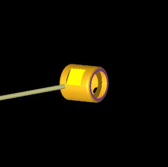
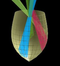
- A new target component type, Multi-Element, is now available. A Multi-Element object is composed of multiple primitives (i.e., elements), which utilize a common set of parameters to specify their Position and Size/Grid information. An example Multi-Element object, composed of 4 rectangles and 4 partial disks (each with a non-zero thickness), is shown below.
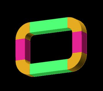
Elements which can be added to a Multi-Element target component include: Box, Cone, Cylinder, Disk, Polygon, Rectangle, Sphere, Spokes, Surface of Revolution, and Torus.
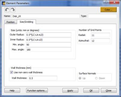
Analytic expressions can be used to specify Element Position and Size/Grid parameters (see below right), where the function variables are those of the parent Multi-Element object. Then, when the values of the Size/Grid parameters of the parent Multi-Element object are changed (LA, LB, LC,...NA, NB,... in below left widget), the Position and Size/Grid values of each of its child Elements are automatically changed. Using this approach, relatively complex objects -- such as the those shown in the image above -- can be easily built and modified.
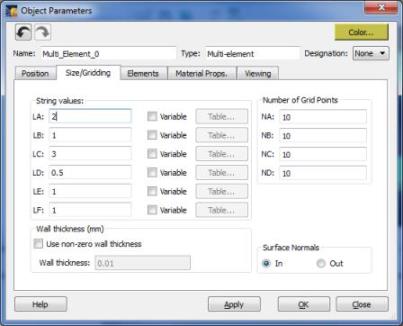
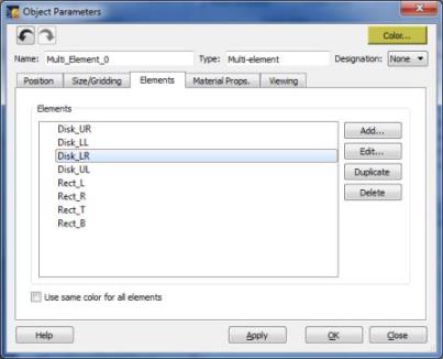
Elements for Multi-Element objects can be added, edited, duplicated, and deleted in the Elements tab of the Object Parameters Dialog. The color of the Elements can be set individually, or be overridden to use the color of the parent Multi-Element object.
Like other types of Target Components, Multi-Element objects can be stored in a user's Target Components Library for later re-use.
- Surface of Revolution Objects: In previous versions, the string expression used on the Size/Gridding tab for Surface r(z) was always defined in units of "cm". Now, if units are specified to be "mm" (set on the User Interface tab of Preferences), string expressions are converted to reflect their value in "mm".
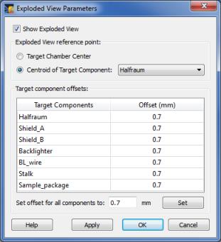
- The capability to show Exploded Views of Target Components in the Main Graphics Window has been added (example shown below). In an exploded view, each component is offset from its original position by a distance that can be adjusted by the user. The direction of the offset is determined by the vector from the position of the component's centroid to a reference point, which is either Target Chamber Center or the position of another Target Component.
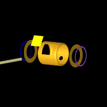
The properties of the Exploded View can be adjusted by selecting the Set | Exploded View Properties menu item. The offset distance for each Target Component can be set individually. Alternatively, the offsets for all components can be set to the same value by entering a value at the bottom and clicking the Set button. Displaying the Exploded View can also be done using the Show | Exploded View menu item.
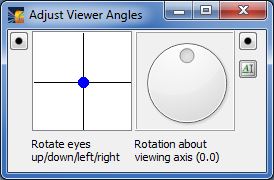
- Viewer Orientation Controls: A precise value of the rotational angle can now be set by the user. When clicking on the (
 ) icon in the Adjust Viewer Angles dialog, the rotation angle can be specified in the edit box that is displayed.
- VISRAD now uses an updated version of its third-party user-interface library.
- When closing a VISRAD application on Mac and Linux systems, the Main Window geometry is now saved and used the next time a VISRAD application is started. (Previously, this was done only on Windows platforms.)
- A warning is now presented if a user attempts to rename an object to that of another existing object. (Object names must be unique.)
- Target Positioning Viewers: The Target Components in the views are now always rendered with surfaces filled front and back, and using either grayscale or target component colors as displayed for the Grid in the Main Graphics Window. (Colors associated with other displays - e.g., Radiation Temperature - are not used).
- The default cache size for holding view factor results has been increased from 10 MB to 500 MB. This value can be adjusted on the View Factors tab of the Preferences dialog.
- Bug fixes:
- A bug causing program to crash when doing a double-click-drag in the Target Components List has been fixed.
- When using the measuring tools (for distance or angle) in the Target Positioning Viewer, the location of the rendered measuring tools is now corrected for translations performed in each view (using
 ) .
) .
- When moving the splitter to change the size of the Main Window Graphics Frame, the OpenGL graphics is now refreshed.
- During batch runs, the view factors cache size is now automatically updated to ensure it has sufficient memory available.
- When rendering on 64-bit Mac platforms, the screen image is now correctly centered when the window is resized to have a large width. The upgrades also fix problems associated with the picking of surface elements on this platform.
Version 12.0.0
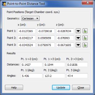
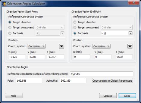
- A tool has been added to facilitate positioning target components. The Orientation Angles Calculator can be used to compute the Polar and Azimuthal Orientation Angles entered in the Position tab of the Object Parameters Dialog. To access the tool, click on the (
 ) button located on the right side of the Orientation Angles box. To use the tool, specify the Start and End point positions for a direction vector that represents the z-axis of the object. When the Update button is clicked, the Polar and Azimuthal angles are computed and displayed, and can be copied to the Object Parameters Dialog by clicking on the Copy Angles... button.
- It is now possible to designate a Cylinder or Cone to be a Stalk object. The purpose of this is to better support the use of Target Mounts in the Target Positioning Viewer. This designation is needed in order to map the position of a target component used to represent a stalk in an experiment (set up in the Main Graphics Window) to the Target Positioner Rotation/Translation controls used in the Target Positioning Viewer. Without this mapping, when the user utilizes a stalk that is offset from TCC (i.e., the axis of the stalk does not point at TCC), the determination of the location of the target mount axis is problematic.
- A target component is designated to be a Stalk object by setting its Designation in the Object Parameters Dialog, and using a Target Mount as its Reference Coordinate System.
- When an object is changed to be designated a Stalk, or when the position of a Stalk object changes, the Target Mount translation offsets in the Target Positioning Viewer are automatically updated to be consistent with the stalk's position in the Main Graphics Window.
- Below are comments on the use of Stalk objects. Note that if not using the Target Positioning Viewer, there is no need to be concerned with Stalk objects.
- Each Target Mount that is being used as the Reference Coordinate System for any target component must have one (and only one) object designated as a Stalk object.
- A Stalk must be either a Cylinder or a Cone. Its z-axis should be closely aligned with the Target Mount axis (i.e., its axis should point toward the center of the Target Mount's port).
- The position of the Stalk object is used to set default Translation values for the Target Mount in the Target Positioning Viewer.
- Any time there is a change in the position of a Stalk object that is attached to a Target Mount, the Translation values for that Target Mount in the Target Positioning Viewer are automatically updated to be consistent with the position of the Stalk object.
- In the Target Positioning Viewer, the Target Positioner "z" translation value defaults to zero and the Rotation value is unaffected by the re-positioning of the Stalk object.
- The use of support tools, such as the Orientation Angles Calculator, the Line-Target Intersection Points Tool, and the Coordinate Transformation Tool, can facilitate positioning a Stalk object with respect to other target components (Examples of this is shown in the documentation: see Designating Objects as Stalks and the updated sample problem on Hohlraum with Multiple Target Mounts).
- Warning messages appear when a Target Mount is used by one or more objects, but no object is designated to be a Stalk for that Target Mount. The stalk-related warning messages can be permanently turned off in the Warnings tab of the Preferences dialog.
- Object Parameters Dialog, Position tab:
- The Target Chamber label has been changed to Target Chamber/Mount to reflect the fact that Target Mounts are selectable under it.
- When changing the Coordinate System in the Position box (e.g., from Cartesian to Spherical), the position values are automatically updated such that the position vector is maintained even if the "Automatically Update Position" option is not checked. This feature can be turned off in the User Interface tab of the Preferences dialog.
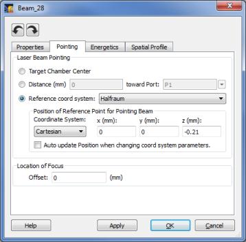
- Laser Parameters Dialog, Position tab:
- When changing the Coordinate System in the Position of Reference Point box (e.g., from Cartesian to Spherical), the position values are automatically updated such that the position vector is maintained even if the "Automatically Update Position" option is not checked. This feature can be turned off in the User Interface tab of the Preferences dialog.
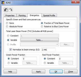
- Energy normalization can now be applied to laser beam powers which use a power specification type of Variable; i.e., when beam powers are specified using a power vs. time table. (Previously, energy normalization could only be utilized for beams using the Profile power specification type.) This has been added to support reading in laser beam energies and time-dependent powers from data files. When the Normalize to Beam Energy box is checked, the table powers are scaled such that the time-integrated power equals the normalization energy. (For more information, see documentation on Importing Laser Beam Data.)
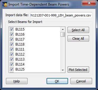
- Support for importing time-dependent laser beam powers from CSV-formatted files has been added, and tested using a sample data file from NIF. To import beam power data into VISRAD, select File | Import Laser Beam Data | Time-Dependent Powers.
- When importing the data, a list of beams for which power data is found is displayed.
- Details of the file format are provided in the VISRAD documentation.
- The time-dependent power data for all selected beams is read in and stored, and the power specification type is set to Variable (i.e., each beam is specified to use tabular time-dependent powers).
- If the power at any time is negative, its value is set to zero.
- For NIF, the imported powers are assumed to be blue cone powers. Red and green cone power parameters are unaffected when importing the data.
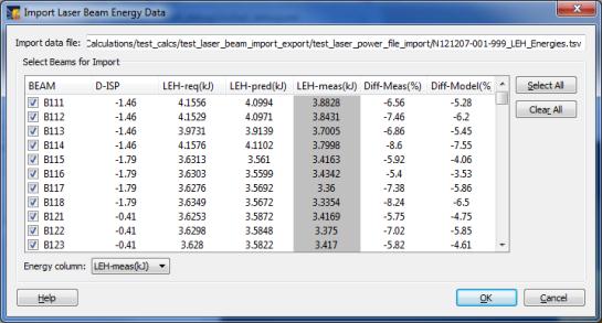
- Support for importing laser beam energies (i.e., time-integrated powers) from TSV- and CSV-formatted files has been added, and tested using a sample data file from NIF. To import energy data into VISRAD, select File | Import Laser Beam Data | Energies for Normalization. Energy data are used to normalize the time-dependent beam powers of each beam such that their time-integrated powers equal their input energies.
- When importing the data, a list of beams for which energy data is found is displayed. Data are displayed in a multi-column table. The energy column to be imported is specified using the combo box at the bottom of the table.
- Details of the file format are provided in the VISRAD documentation.
- The energy data for all selected beams is read in and stored, and the beam power is set up to Normalize to Beam Energy (i.e., for each beam read in, its time-integrated power will be normalized to the input energy).
- If a beam energy is negative, its value is set to zero.
- For NIF, the imported energies are assumed to be applicable to the blue cone powers.
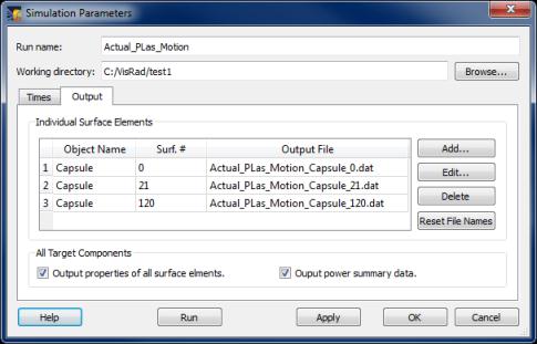
- Multi-Timestep Simulations: Surface element data and power summary data can now be automatically written to output files during multi-timestep simulations (whether performed using the GUI or in batch mode). This is controlled on the Output tab (previously named Surfaces tab) of the Simulation Parameters widget (displayed using the Simulation | Configure menu). At each time step, the surface element data and power summary data are written to separate files.
- CAD Files/Generalized Mesh objects:
- When importing a CAD file, the rendering is set to fill both front and back of surface elements.
- Target component data can now be exported to a CAD file using a variety of common units (m, cm, mm, microns, inches).
- A bounding box for GENERALIZED MESH objects can now be displayed in the Main Graphics Window. The bounding box is established using the maximum and minimum values of the x, y, z coordinates of the nodes for the object. To display GENERALIZED MESH bounding boxes, selected the Show | Bounding Boxes (GM objects) menu item. The colors of the edges of the bounding boxes are red, green, and blue for the edges that are parallel to that object's x-, y-, and z-axes, respectively.
- In the Surface Elements Data (*.sed) files, the simulation time is now written near the top of the file. The format ID for the file has been updated to support backwards compatibility for readers developed by VISRAD users.
- When displaying the key point positions of a particular target component using the () tool button on the right side of the Main Graphics Window, the view in the Target Component Positions Dialog is scrolled to the picked object.
- VISRAD Main Window (Windows platforms only): Whether the Main Window is in a Maximized state is now tracked along with the non-maximized window size. When starting a new instance of VISRAD, the window is restored either to its maximized state, or its non-maximized window size.
- Bug fixes:
- A problem occurring when starting VISRAD without an existing preferences file has been fixed.
- A bug which could occur when showing both rendered beams and the beam spot overlays in the Main Graphics Window has been fixed. If both were displayed, the rendered beam size could be inaccurate immediately after doing a laser power deposition calculation. The rendered beam size parameters are now updated appropriately.
- When performing multi-timestep simulations using the Simulation | Run menu item without first displaying the Simulation Parameters dialog, the run name and working directory are now updated appropriately.
- A Help page for importing laser beam pointing data has been added to the documentation.
Version 11.5.0
- Memorized Views: Support for saving viewing parameters of the Main Graphics Window has been added. This allows users to conveniently set up a list of custom views, and quickly recheck views from commonly used viewing angles. For each Memorized View, the following parameters are stored:
- Viewer and scene positions (parameters from the Set Viewing Parameters widget
- Rotational angles from the Adjust Viewer Angles widget
- Mouse-controlled zoom, rotation, and translation parameters from the Graphics Viewing Controls
- Parameters associated with the Scene Rotation Controls.
To access the list of Memorized Views, select the Edit | Memorized Views List menu item.
- Parameters in the Adjust Viewer Angles widget are now saved to the workspace file.
- OMEGA EP:
- TIMs #10 - #14 have been added to the list of available Target Mounts.
- The list of Diagnostic Ports has been updated.
- ORION:
- The ORION target chamber has been re-oriented. The z-axis, or "up" vector now points to Port 41 (Target Inserter).
- When opening an old workspace file that uses the ORION chamber, a message is displayed notifying the user of the re-oriented chamber.
- TVS-1 and TVS-2 Viewers are now supported. To show the ORION TVS Viewer, select the View | TVS-1/TVS-2 Viewer menu item.
- The CAD file for the ORION target chamber component has been updated (located in /data/chambers/orion). It is based on CAD file provided by AWE and is now oriented correctly.
- ORION TIMs (TIM17, TIM44, TIM46, TIM47, TIM76, TIM104) have been added to the Chamber Components Library.
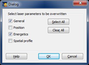
- When importing beam parameters from *.csv files, the user can specify a subset of parameters to be utilized. The parameters are grouped as follows:
- General parameters (beam on/off, cluster ID)
- Position parameters
- Energetics parameters
- Spatial profile parameters
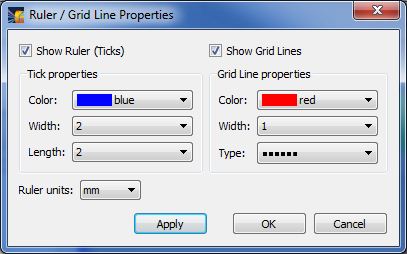
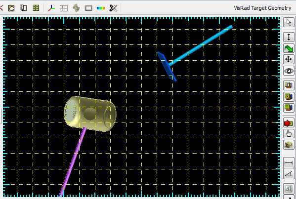
- The characteristics of the Ruler and Grid Lines in the Main Graphics Window and Target Positioning Viewers can now be edited by the user. To support this, the following changes have been made:
- Use the Set | Ruler Properties menu item to change the properties (e.g., color, line width, stipple pattern; see widget below).
- A new tool button (
 ) at top of the Main Graphics Window and Target Positioning Viewer can be used to toggle the visibility of the ruler (tick marks) and grid lines.
- The parameters used for the Main Graphics Window are saved to the workspace file.
- The functionality of the Show | Ruler and Show | Ruler and Grid Lines menu items have been combined.
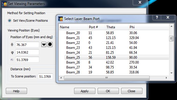
- Set Viewing Parameters widget: The angle for the Viewing Position can now be specified to be that of one of the laser beam ports. Selecting the (
 ) button pops up a list of laser beam ports.
- Target Component Positions dialog: The Reference Coordinate System can now be specified to be that of one of the laser beam ports.
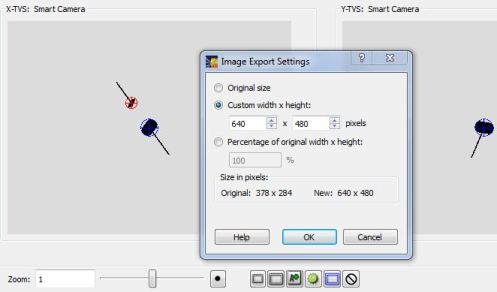
- Target Positioning Viewers:
- Options for the exported image size an any view include:
- Original size
- Specifying a custom number of pixels for either width or height (the aspect ratio remains fixed)
- Percentage of original width and height.
- When exporting an image of one of the OMEGA X-TVS/Y-TVS Camera Views, the default number of pixels is the resolution of the corresponding camera.
- Tooltips have been added to many of the buttons on the viewer.
- Users can now disable the prompt to save the workspace when exiting VISRAD. To do this, select the Edit | Preferences menu item, and uncheck the box on the Warnings tab.
- OMEGA Laser System Phase Plates:
- DPPs for the PD-SG2-600 and E-PD-SG2-600 phase plates have been added.
- The default values for the LLNL phase plate (i.e., the OMEGA LLNL-3w-x50-xxx DPPs) spot sizes have been reduced by a factor of 2 (per instructions from OMEGA OPs team).
- Tool tips have been added to the navigation buttons on the right side of the Main Graphics Window.
- Target Component Key Points (e.g., corners of rectangles and boxes) can now be displayed in the Main Graphics Window. (Previously, they could be shown only in the Target Positioning Viewer.) To show the key points of an object, select the Target Component Key Points (
 ) tool button on the right side of the window, and then select an object in the graphics area. The Target Components Positions Dialog is automatically displayed, and the key points are shown in a variety of colors, which map to those shown in the positions dialog. The size of the key points, as well as the type (and number) of key points displayed, can be specified in the Graphics tab of the Preferences dialog.
- A Bill of Materials can now be exported from VISRAD by LLE users. The file contains the name of each target component, along with its dimensions. To generate the file, select File | Export Bill of Materials.
- Multi-timestep simulations: Support for running simulations in batch has been added. The command line arguments are:
-b : Run in batch mode
-i WORKSPACE: Input workspace file (required)
-o RUNNAME: Run name used in generating output file name for each incident flux surface element (defaults to name set in simulation configuration)
-d OUTPUT_DIR: The directory for the output files (defaults to directory set in simulation configuration)
-x Overwrite existing data files
-h Prints a help message.
- Additional key points have been added for:
- Rectangles with non-zero thickness
- at the waist of cylindrically and spherically symmetric objects at azimuthal angles of 0, 90, 180, and 270 degrees.
- In the Target Positioning Viewer, key points are now shown only if the object is visible.
- The Oracle Database SQL driver has been updated for 64-bit Windows 7 platforms. This now allows direct access to the OMEGA SRF database from Windows 7 PCs.
- Bug fixes:
- A problem where secondary images sometimes erroneously appeared in NIF Target Positioning Views has been fixed.
- A problem which caused VISRAD to report a fatal error when computing view factors has been fixed.
- Target Positioning Viewers: For the NIF and LMJ target chambers, when the Help button is pressed, the correct page in the documentation is now shown.
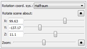
- A bug occurring when saving and reading in non-zero scene rotation angles (Rotate Scene About values in lower left corner of Main Graphics Window has been fixed.
- On Laser Beam Spatial Profile tab, the Rotation Angle widgets are now enabled/disabled properly when the Spatial Profile Model is changed.
Version 11.1.0
- The Diagnostic Ports list has been updated for the OMEGA target chamber.
- 2w/4w Probe Beams for OMEGA and OMEGA-EP: The 2w/4w probe beams that originates from OMEGA port P9 and OMEGA-EP port 71 can now be easily added to the list of available laser beams. To do this, select the Lasers | Add 2w/4w Probe Beam menu item. The beam is added as a Custom beam; it can therefore be deleted and many of its properties are editable.
- Improvements to graphics:
- The quality of text rendered in various plot windows has been improved. This in particular affects Mac and Linux platforms.
- Legends and colorbars are now resizable.
- The ability to reset legends and colorbars to their default position is now available on Surface Element Contour Plots and Incident Spectrum Line Plots. To reset the position, select the Graph | Reset Legend Position menu item of that plot window.
- Surface Element Contour Plots: The default colorbar titles have been shortened.
- Main Window Graphics Frame :
- The Scene Position is now centered in the graphics frame.
- The Color Bar Overlay can now be displayed when using Perspective projection (previously it was only shown when using Orthographic projection).
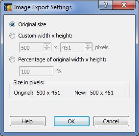
- Exporting images: Images from several of the graphics windows can now be exported with a user-specified number of pixels.
- Windows affected include:
- Main Window Graphics Frame
- Surface Element Contour Plots
- Incident Spectrum Line Plots (for individual, or "picked", surface elements).
- Options for the exported image size include:
- Original size
- Specifying a custom number of pixels for either width or height (the aspect ratio remains fixed)
- Percentage of original width and height.
- Limitations:
- The aspect ratio is held fixed (same as that shown in displayed window).
- Number of pixels: The buffer size, which limits the maximum number of pixels in the image that is exported, is system-dependent. In test cases on a Windows 7 PC, the largest image produced was ~ 20,000 x 12,000 pixels (which is ~ 10 to 20 times larger than images previously exported).
- When exporting an image from the Main Window Graphics Frame, if not exporting as the Original Size, the option to add the color bar widget that is located below the Main Window Graphics Frame is not supported.
- UnDo and ReDo buttons have been added to the Object Parameters dialogs and the Laser Beam Parameters dialogs . Characteristics of UnDo/ReDo operations include:
- The state of widgets is saved onto the UnDo/ReDo stack whenever a widget state changes or whenever the Apply button is pressed.
- When a different Target Component or Laser Beam is selected for editing, the UnDo/ReDo stack is re-initialized.
- UnDo/Redo works for all widgets in the Object Parameters dialogs and the Laser Beam Parameters dialogs with the exception of the tables that hold time-dependent quantities (entered using the Table button).
- The rotation sliders in the lower left corner of the Main Window have been updated to support angle resolutions of 0.01 degrees.
- Preferences on Mac OSX systems: The menu to set Preferences is now located under the Edit menu.
- Size/Distance units in Preferences:
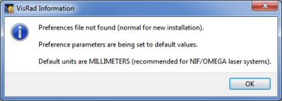
- On startup, a check is made for the existence of the Preferences file. If it does not exist, the user is informed that all parameters set in the Preferences dialog will be set to their default values. This helps prevent situations in which a user installs VISRAD on a new computer, and is unaware that default values for the Preference parameters are now being used. (Note: When installing VISRAD on a new computer, users can copy the Preferences file from the old to the new computer to avoid having to reset parameters. See Preferences File in the Files section of the documentation.)
- The default value for Size/Distance units in Preferences has been changed from cm to mm.
Version 11.0.1
-
Bug fixes:
- Fixed bug associated with bad value for 'GraphicsItems' format ID. Sometimes prevented reading of workspaces generating using Version 11.0.0.
- Fixed bug occurring when saving a workspace without showing Beam Spot Overlay. Beam spot overlay labels were blank, requiring labels to be regenerated using the right-click menu in Main Graphics Window.
Version 11.0.0
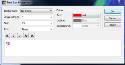
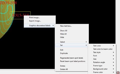
- One or more labels can be selected and moved, duplicated, and hidden/shown. Note that while Beam Spot Overlay labels can be shown and hidden, they cannot be deleted.
- Labels can be re-generated, in which case label text, colors, and font features are set to their default values. Labels can also be reset to their default positions without changing text properties.
- The rendering of intensity contours for beam spots in the Main Graphics Window has been updated to provide for better appearance. The color of the contours can be specified by the user (see Edit | Preferences; Lasers tab).
- The number of angle points used in generating each contour is equal to the number of angle points used in generating the beam cones in the Main Graphics Window, which is set in Preferences (Lasers tab).
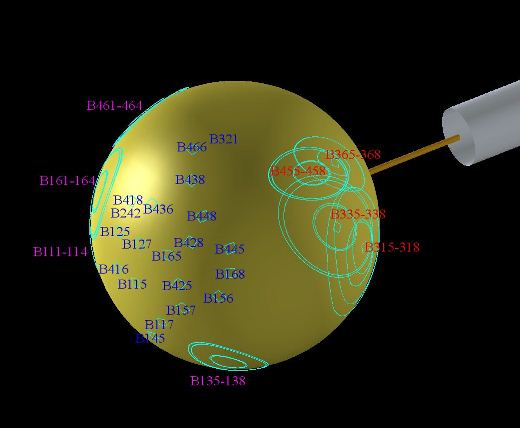
- Beam Spot Overlay label properties for the Main Graphics Window are saved to workspace.
- In Preferences (Lasers tab), options for 90%, 99%, and 99.9% intensity contours have been added.
- Beam Spot Overlay labels in Surface Element Contour Plots have also been updated, using an approach similar to that described above for the Main Graphics Window.
- In Surface Element Contour Plots, beam spot display operations are now located under the new Beam Spots menu. Menu items have been added to re-generate and reposition labels. The spot color can also be set using the Beam Spots menu.
- Beam spot label properties can be set by either double-clicking on a label or selecting one or more labels and right-clicking to bring up menu options (similar to the Main Graphics Window).
- Text boxes are now not hidden in Main Graphics Window when Perspective viewing is in use (previously, text boxes were only shown for Orthographic viewing).
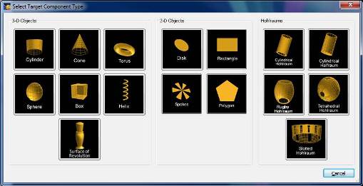
- A new type of target component, a "Surface of Revolution", is now available. This is an object that is cylindrically symmetric about the z-axis, and the radial location of the surface, r, is specified as a function of the z position using an analytic expression.
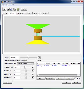
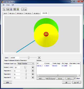
- A Target Alignment System (TAS) Viewer has been added for the LMJ target chamber. There are views from 6 angles which support target alignment for the LMJ. The viewer includes the ability to manipulate the views (zooming, rotation), utilize length and angle measuring tools, and add and edit reticles.
- The beam cone transparency in the Main Graphics Window is now editable. It can be set for a single beam in the Properties tab of the Laser Beam Parameters dialog. It can also be set for one or more selected beams in the Laser Beams List by right-clicking and selecting the Set Transparency menu item, or selecting the corresponding menu item in the Lasers menu at the top of the window.
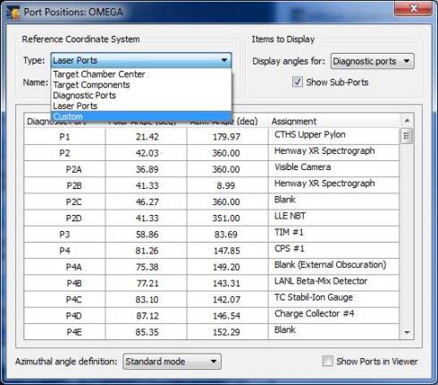
- Viewing target chamber port positions:
- The Port Positions table widget, which shows the angles to laser and diagnostic ports in a variety of reference coordinate systems, has been updated.
- More options are available for specifying the Reference Coordinate System. The coordinate systems of laser and diagnostic ports have been added. A Custom coordinate system can be specified.
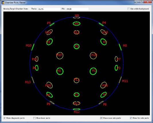
- A Chamber Ports Viewer has been added which graphically displays the port positions using the specified reference coordinate system.
- To display the viewer, check the Show Ports in Viewer box.
- Laser ports and diagnostic ports can be displayed separately.
- The far-side and near-side ports are displayed using different colors and can be displayed separately.
- The size and shape of the ports are not modeled accurately; only the locations.
- Labels in the Chamber Ports Viewer can be moved and edited by selecting with the mouse and using the right-click menu.
- In the table, there are now two modes used in displaying the azimuthal angle of a port in the reference coordinate system. The "standard" mode, which has been used in previous versions, uses a conventional spherical polar coordinate system. The LLE View Tank mode uses a definition in which the azimuthal angle is the angle about the viewing axis, measured relative to 12 and 6 o'clock, with angles ranging from -90 to +90 degrees (both straight up and straight down are zero).
- When double-clicking on a target component in the Main Graphics Window, if the Object Parameters Dialog is hidden beneath other windows, it is now brought to the top.
- Exporting and printing images has been updated to eliminate problems which occurred on Mac systems running OS 10.6 (similar problems do not occur for OS 10.5 and 10.7).
- When exporting images, the default folder for exporting is the last folder that was accessed.
- The documentation for Troubleshooting was updated to address the problem of VISRAD not starting up due to a corrupted user preferences file (.visradrc).
- Bug fixes:
- Fixed crash in Target Positioning Viewer which occurred when a new reticle was being added and moved with mouse, but Cancel is then pressed in the Reticle Parameters Dialog.
- When computing contours for Beam Spot Overlays in the Main Graphics Window, a bug which sometimes occurred when the beam focus point was very close to the target surface, and resulted in a non-continuous contour pattern, has been fixed.
| Copyright © 2000-2026
Prism Computational Sciences, Inc. |
VISRAD 21.1.1 |