Revision History
Shown below are VISRAD revision summaries for:
Version 16.1.1
- When showing enhanced laser beam radii for 3w/1w Capture or Clearance in the Main Graphics Window (Lasers | Show Enhanced Radius menu item), the intensity fraction (I/I0) used in defining the beam radius is now taken to be the corresponding threshold value specified in the Capture/Clearance Setup Parameters dialog box. This overrides the value of I/I0 specified with the Lasers | Radius in Display menu item. To avoid confusion, a warning is shown when the radius in display is adjusted while enhanced radii are being shown.
- Bug fixes:
- When zooming with the mouse wheel (where behavior was modified in VISRAD 16.1.0 so that in Orthographic projection zooming occurs towards or away from where the mouse is pointed):
- the grid and tick mark spacing is now updated for wheel zooming;.
- the distance measurement tool (performed using the (
 ) toolbutton) now takes into account the wheel zooming.
Version 16.1.0
- Several features have been added to improve manipulating the view in the Main Graphics Window:
- When zooming with the mouse wheel while using Orthographic Projection, (Show | Orthographic Projection menu item), the zooming occurs towards or away from where the mouse is pointed. When in Perspective Projection, zooming with the mouse wheel behaves same as previously.
- Space mouse support has been added. Testing has been performed using 3DConnexion space mouse. Zooming, translations, and rotations are supported. (As with zoom with the mouse wheel, when in Orthographic Projection, zooming occurs towards or away from where the mouse is pointed.)
- Zooming with the mouse wheel can now be done when in Translation mode (
 tool button).
- Clicking on a Target Component in the Main Graphics Window:
- The Key Points of the component are now displayed, and the last target component picked is stored.
- Three items have been added to the right-click menu:
- View Object is used to sets the viewing position relative to the last picked Target Component (e.g., top/bottom or front/back)
- Rotate About Object is used to set the Rotation Coordinate System to that of the last picked Target Component. This is utilized by the sliders in the lower left portion of the Main Window.
- Set Viewing Position is used to set the view position (same as the Set | Viewing Position menu item).
- In Preferences (Graphics tab), the default projection model has been changed from Perspective to Orthographic. Orthographic projection is generally better for manipulating the view in the Main Graphics Window.
- Picking on Chamber Components in the Main Graphics Frame is now supported.
- Double-clicking on a Chamber Component brings up the Chamber Component Parameters Dialog.
- Displaying node positions for picked surfaces of Chamber Components, using either the (
 ) or (
 ) tool buttons, is now supported.
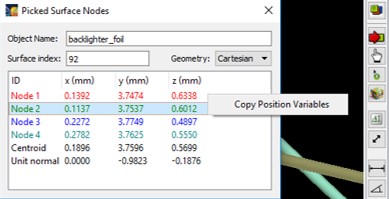
- To copy position variables from the Picked Surface Nodes widget into other widgets with position variables, which is displayed using the () tool button, users can now right-click on one of the listed nodes, and select the Copy Position Variables menu item. When this is done, all 3 position variables are copied, and the geometry (Cartesian, cylindrical, or spherical) is tracked. When pasting into boxes using a different geometry, the position variables are converted to that geometry.
- Double-clicking on one of the listed nodes populates position data fields in the Point-to-Point Distance Tool.
- Laser-Target Capture/Clearance Report: When showing only non-cleared surface elements for a laser beam, the cleared surface elements can also be displayed as semi-transparent elements.
- Parameters which set the transparency are on the Config. Checks tab of Preferences.
- Target Positioning Viewers: The ability to display beam spots overlay has been added. To do this, select the Show | Beams Spots Overlay menu item in the viewer. Labels for the beams are now displayed. The properties of the beam spot contours are specified in the Beam Spots Overlay box on the Lasers tab of Preferences.
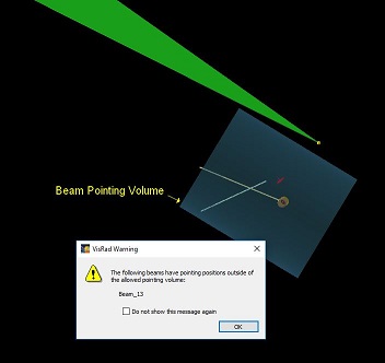
- OMEGA Target Chamber: Checks on laser beam pointing are now performed. Beam pointing is limited to a cylindrical volume: 10 mm off-axis orthogonal to the beam direction and +9 / -15 mm along the beam propagation direction.
- Pointing checks are performed each time laser beam and target component parameters are edited (the latter because beams can be pointed relative to target components).
- Beam pointing checks can also be performed using the Lasers | Perform Beam Pointing Checks menu item.
- Checks are not performed on probe beams, beams entering from EP ("Beam_EP"), or custom laser beams.
- Warnings can be turned off either by checking the box in the warning message, or in Preferences on the Warnings tab.
- OMEGA X-TVS/Y-TVS Viewer :
- The ability to export silhouette images of the beam spots overlay (i.e., with a transparent background) has been added. To do this, select the File | Export Image | 1-bit N/W Views - Beam Spots menu item. The properties of the beam spot contours are specified in the Beam Spots Overlay box on the Lasers tab of Preferences. The beam spots are shown with 100% opacity.
- When exporting 1-bit N/W views, it is now possible to adjust the color of the silhouette images of targets. The color used is specified in Graphics tab (Target Positioning Viewer box) in Preferences.
- OMEGA SRF Beam Parameters: The maximum allowed pointing radius has been increased from 10 mm to 15 mm.
- NIF TaLIS Checks Controller:
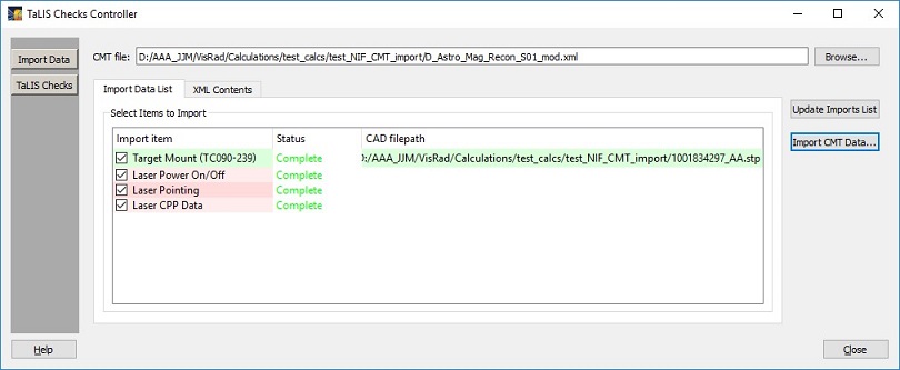
- The order on the Import Data List tab has been changed so that the laser data is listed first.
- Exporting results of TaLIS checks to a file is now supported. To do this, click on the Export Results button in the NIF TaLIS Checks Controller.
- ORION Target Chamber: The names of the backlighter beams have been switched. "Backlighter_1" now enters through Port 48, "Backlighter_2" through Port 36.
- In the laser power calculation, the size of the envelope considered for the beam (set in the Advanced Beam Cone Parameters box of the beam's Spatial Profile parameters tab) is now limited to a value based on the supergaussian parameter. This parameter is used in generating a grid of test rays used to compute the fraction of laser beam power is hitting the target grid.
- Bug fixes:
- Displaying Direct Laser Power Deposited: when computing powers for AMR Grids, results are no longer stored in memory associated with results for the power computed for Standard Grids. This sometimes led to inconsistencies when displaying and utilizing the results for Standard Grids.
- When displaying Key Point positions of Target Components, a bug causing the mouse cursor to be reset and the key points to disappear has been fixed.
- Bug causing crash when exporting target components to a CAD file, in which the target component has a clipping volume whose reference coordinate system is that of a previously deleted target component, has been fixed.
- Bug causing crash when importing data from a CAD file on Linux has been fixed.
- Fixed bug where the Picked Surface Node Positions tool was not being displayed for the index = 0 surface element of Target Components.
- NIF TaLIS Checks Controller: the problem with check boxes on the Import Data List has been fixed.
Version 16.0.0
- Support has been added for the SLAC MEC target chamber:
- 4 beams have been added to the Laser System: X-ray beam (fixed in Port P 90-180), 2 movable Nd:Glass (long-pulse) beams, 1 movable short-pulse beam.
- Angles for Diagnostic Ports: Ports are identified by their angle with respect to target chamber center (e.g., P 90-180) has a polar angle of 90 degrees, and azimuthal angle of 180 degrees.
- Laser Beam Capture/Clearance Calculations:
- 1w (red cone) Footprint Calculations can now be performed for NIF. In these calculations, any portion of the target mesh on which two or more red cones overlap are tracked.
- Results are displayed in the Main Graphics Frame (either shown automatically after a calculation, or using the Display | 1w Cone Overlap menu item).
- A summary of the results are tabulated in the Capture/Clearance Reports dialog on the 1w (red cone) Footprint Report tab.
- Enhanced laser beam cone radii are utilized (set using Min. Target Clearance in Red (1w) Cone Clearance / Footprint box; see below).
- The section used to set parameters for the capture/clearance calculations and the section used to show results have been separated into two different widgets (left and right widgets shown below):
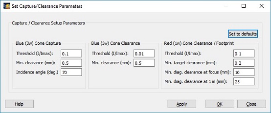
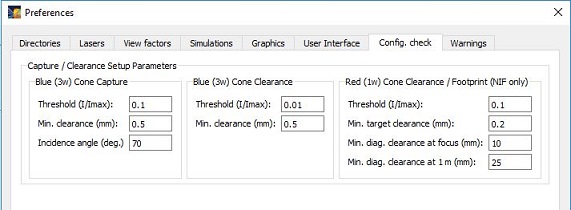
- Default setup parameters for laser beam capture/clearance have been added. Default values are stored in Preferences on the Config. Check tab (see below). When clicking on the Set to Defaults button on the Set Capture/Clearance Parameters dialog, the default values for the setup parameters are loaded.
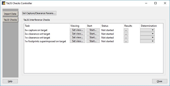
- NIF TaLIS Interference Checks: A new controller for supporting TaLIS Interference Checks has been added (see below). To access the TaLIS Checks Controller, select the NIF-OPS | TaLIS Checks menu item.
- Supported checks include:
- Capture of 3w beams on target
- Clearance of 3w beams for Target and Chamber Components
- Clearance of 1w beams for Target and Chamber Components
- 1w Footprint on target
- For each calculation, the following are supported:
- Setting the default view in the Main Graphics Frame
- Starting the calculation
- Showing the calculation status (In progress, Pass, Fail)
- Showing tabulated results in the Capture/Clearance Reports dialog
- NIF CMT XML file support:
- The ability in input target and laser beam data from NIF CMT XML files has been added. Supported data includes:
- Target Data
- Target STP file associated with each target mount
- Laser Beam Data
- Beam On/Off Data
- Pointing Data:
- Pointing position, with pointing provided in Cartesian (x,y,z) coordinates in the target chamber coordinate system.
- Defocus (a positive value moves the lens towards the target)
- For both position and defocus variables, units of "cm", "mm", and "um" (microns) are supported.
- Phase Plate (CPP) Data:
- The command line for VISRAD startup has been updated to support accepting a NIF CMT XML file as input. The filename follows the "-n" switch (e.g., -n qsNifCmtXmlFilename). Details for command line startup for VISRAD is provided in the documentation.
- Preferences: default directory for target CAD input files identified in the CMT XML file has been added on the Directories tab.
- NIF Laser Beams: The default values for the power in the red (1w) and green (2w) cones have been changed to have non-zero values. For each cone, the new default value is 5% of the total cone power. (Default values are only utilized for new workspaces.)
- Two NIF Phase Plates (CPPs) have been added:
NIF CPP |
HWHM R-major (mm) |
HWHM R-minor (mm) |
Supergaussian n * |
No CPP |
75 |
75 |
2.0 |
400 um CPP |
189 |
189 |
7.145 |
- Importing CAD Files:
- Importing more than one CAD file at a time is now supported (using the File | Import CAD Files menu item).
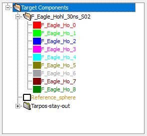
- When importing a STP-formatted CAD file as a Target Component, if the CAD file contains more than one object (or "shape"), a reference object is automatically set up, and each of the CAD objects use this reference object as their Reference Coordinate System. This allows users to easily rotate or translate the entire set of CAD objects. The reference object is a small Cone object that is hidden when set up, and it is set to be ignored in laser deposition and radiosity simulations.
- When importing STP CAD files, progress messages are posted on the bottom of the Main Window.
- Support for changing the Reference Coordinate System for multiple Target Components has been added. To do this, right-click on the Target Components List and select the Set Ref. Coord. System menu item.

- Display of Laser Beams in Main Window:
- The ability to show laser beams with an enhanced radius can be done using the Lasers | Show Enhanced Radius menu item.
- Enhanced radii values for the Fixed submenu item are set in the Clearance Report tab (Show in Main Window box) of the Capture/Clearance Reports dialog, and in the SRF Laser Parameters widget for OMEGA.
- Enhanced radii values for other submenu items are set in the Set Capture/Clearance Parameters widget.
- The ability to limit the extent (distance from focus) for which laser beam cones are rendered has been added. To do this, select the Edit | Preferences menu item, and on the Lasers tab, set the value for Limit display of beams from focus. For NIF, this affects blue (3w) cones only.
- Laser Beam Spot Overlays: The ability to adjust the thickness of contour lines for the beam spot overlays has been added. To do this, select the Edit | Preferences menu item, and on the Lasers tab, set the value for the Line Thickness in the Beam Spot Overlays box.
- Target Positioning Viewer: For NIF, the limits for x, y, and z translations have been increased from 10 mm to 30 mm.
- Chamber Component Parameters Dialog: Size/Gridding tab was added. This shows the number of surface elements and nodes that make up the Chamber Component, and its min/max x, y, and z node positions in the target chamber coordinate system. All values are not editable.
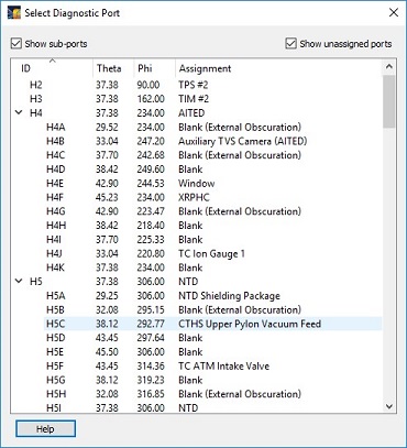
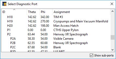
- The Diagnostic Ports Selector, which is used by several dialogs to select the angles of a diagnostic port, has been updated.
- Check boxes are now at the top, and are used to show or hide sub-ports and unassigned ports. Unassigned ports are those that have Assignment string that is empty, or starts with either "Blank" or "Unassigned".
- The sub-ports of individual ports can be expanded or collapsed by clicking on the icon to the left of the port ID. However, this capability is not available when sorting by other than the ID column.
- The list can be searched by right-clicking in the list and selecting the Find menu item.
- Copy/paste of position variables: It is now possible to copy and paste position variables between dialogs. When this is done, all 3 position variables are copied, and the geometry (Cartesian, cylindrical, or spherical) is tracked. When pasting into boxes using a different geometry, the position variables are converted to that geometry. (Note: conversions to not take into account the Reference Coordinate System used for the position variables.) To do this, right-click on any of the 3 position boxes, and selected Copy (Paste) Position Variables. Affected dialogs include:
- Object Parameters Dialog - Position tab
- Laser Parameters Dialog - Pointing tab
- Clipping Volume Parameters Dialog - Position tab
- Coordinate Transformations Tool
- Line-Target Intersection Points Tool
- Point-to-Point Distance Tool
- Orientation Angles Calculator
- Set Viewing Position Dialog - Scene position
- Target Component Positions Dialog - copy supported
- OMEGA X-TVS/Y-TVS Viewer: When exporting 1-bit N/W views, it is now possible to adjust the transparency of the silhouette images. The transparency used is specified in Graphics tab (Target Positioning Viewer box) in Preferences.
- Bug fixes:
- Set Viewing Parameters dialog: bug associated with setting the Scene position when using cylindrical geometry has been fixed.
- A problem that caused a crash to occur when importing STP-formatted CAD files has been fixed.
- A problem that prevented the f-number of custom laser beams to be edited has been fixed.
- Crash that sometimes occurred when adding a GENERALIZED_MESH target component to the Chamber Components List has been fixed.
Version 15.0.0
- A report showing which laser beams are fully captured by the target grid can now be generated using the Laser Beam Capture Report. To generate a report, select the Lasers | Capture/Clearance Assessment, or click on the
 tool button.
A laser beam cone is considered to be fully captured by the target grid if both the "boundary" of the beam cone is fully contained within the target grid and it hits the target surface at an incident angle which is less than a specified allowed maximum. The beam cone is given an enhanced radius to ensure a that minimum clearance is maintained.
In performing laser beam capture calculations, only Target Components are considered in the calculation. Chamber Components are ignored. Also, calculations are performed only for blue (3ω) cones; for NIF, calculations are not supported for red (1ω) and green (2ω) cones.
The beam capture report contains two tables: one containing the beam "capture fraction", the other containing the maximum allowed incidence angle.
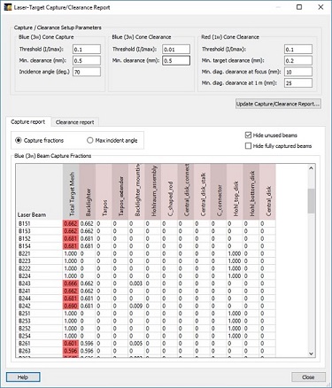
The capture fraction is the fraction of test rays that are incident on the grid of Target Components (see table above, left). For each beam cone, a grid of rays extends from the laser beam final optic toward the beam focus. The intersection of each ray with the target grid is then computed, and the number of hits on each Target Component is tallied. The fraction of rays hitting each target component is shown in the table, as well as the total for the target mesh. If the capture fraction for the total mesh is less than one, the result is highlighted.
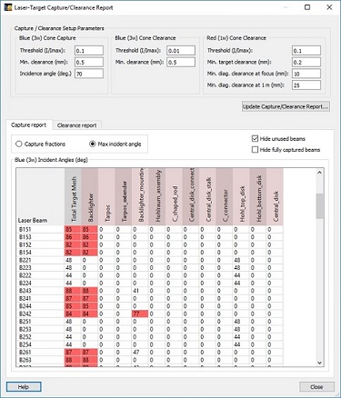
For each ray hitting a surface element of a Target Component, the angle with respect to the surface normal is computed. The maximum angle recorded for each Target Component is then reported in the incident angle table (see table above, right). If the maximum incident angle exceeds the value specified by the user, the result is highlighted.
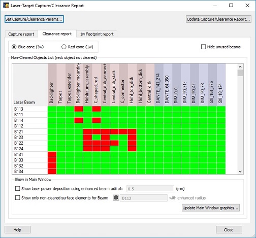
- A report showing which laser beams clear Target Components and Chamber Components can now be generated using the Laser Beam Clearance Report. To generate a report, select the Lasers | Capture/Clearance Assessment, or click on the tool button.
A laser beam cone is considered to clear a Target Component (or Chamber Component) if none of its surface elements is contained within a cone test volume which is specified using: (1) the intensity threshold (I/Imax), which is used to define the outer radius of the beam cone, and (2) a minimum clearance, which is the amount by which the cone radius is expanded
For each laser beam cone, all Target Components and Chamber Components are checked to see if any of their surface elements lie within the test volume. If any surface elements lie within the test volume, the component fails the clearance test. The beam clearance report contains a table showing, for each beam cone, which Target Components and which Chamber Components are either cleared (shown as green) or not cleared (shown as red). This allows users to easily see which items fail the clearance test for each beam.
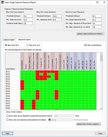
Input for the blue (3ω) clearance calculations include the intensity threshold to use in defining the outer radius of the cone test volume, and the amount by which the test cone radius is enhanced. This enhancement to the cone radius is applied along the entire length (z-axis) of the cone.
For red (1ω) clearance calculations (for NIF), separate clearance parameters are applied to Target Components and Chamber Components. For the value specified for Target Components, the enhancement applied to the test volume is constant along the cone axis. For Chamber Components, the enhancement to the radius varies linearly with z (i.e., the distance from the focus). In this case, the clearance is specified using two parameters:
- the minimum diagnostics clearance at focus, and
- the minimum diagnostics clearance at 1 meter.
Additional parameters that affect the cone test volume are the number of angular (i.e., azimuthal) points, and the number of points along the z-direction (see the Lasers tab in Setting Preferences).
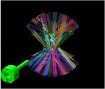
Additional information regarding beam clearance can be obtained using the check boxes at the bottom of the Laser Beam Clearance Report. The laser power deposition intensity on the target grid (i.e., Target Components only) can be shown in the Main Window, where the radius of each beam's intensity profile is enhanced by a specified amount. (If the enhanced radius is zero, the results are the same as obtained when selecting the Display | Direct Laser Power Deposited.)
Also in the Main Window, the surface elements of Target Components and Chamber Components that lie within the cone test volume of a specified laser beam can be displayed. To do this, check the box, and click on the Update Main Window Graphics button.
- When importing CAD files, the following changes have been made:
- When importing a STEP-formatted CAD file as a Chamber Component:
- individual CAD objects (or CAD "shapes") are separated into items within a single Chamber Component.
- each item is given a separate color, and placed in the Chamber Component, whose name is given by the imported file
- the names of the individual items are truncated, and appended with a number.
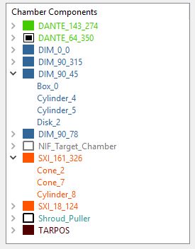
- Chamber Components List: An icon now appears to the left of each chamber component name. Its appearance signifies the following:
- Color and filled: Chamber component is included in laser beam clearance calculations; it is shown in the main window.
- Color and open: Chamber component is included in laser beam clearance calculations; it is hidden in the main window.
- Black and filled: Chamber component is not included in laser beam clearance calculations; it is shown in the main window.
- Black and open: Chamber component is not included in laser beam clearance calculations; it is hidden in the main window.
- NIF Target Chamber: The TanDM348 has been added to the list of available Target Mounts.
- Chamber Components Library: when importing Chamber Components from the library, the components are now always shown, even if they were hidden when saved to the library.
- OMEGA X-TVS/Y-TVS Viewer:
- When exporting reticle data to XML-formatted files, the reticle name is now defined using "ret_name", and leading zeros have been dropped for reticle position and ellipse angle orientation variables.
- When exporting 1-bit N/W views, the Wide view now correctly exports 2248x2248 pixel images.
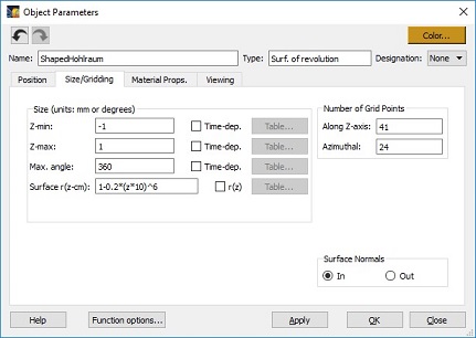
- Surface of Revolution object: Updates have been added to support specifying the z-dependent Surface of Revolution radius using a table of r and z values. At each node of the surface, the radius is computed by interpolating using the node's z-position.
- Object Parameters Dialog, Size/Gridding tab: The text of check boxes used to specify time-dependent grid sizes has been changed from Variable to Time-Dep. For Surface of Revolution objects, the check box is used to supply r(z) values.
- Chamber Components List: Support has been added to set the color of Chamber Components or any of their items. To do this, right-click on one or more items in the Chamber Components List, and select the Set Color menu item.
- When displaying Cutaway Views in the Main Graphics Window, negative offsets can now be used.
- Laser Beam Parameters Dialog: On the Properties tab, for "fixed beams" (i.e., non-Custom beams), the port position boxes were changed from "disabled" to "read only". This allows users to copy port angles and paste them into other edit boxes.
- Bug fixes:
- OMEGA SG5 Phase Plate: the spot size ("Major radius at best focus") was changed to its correct 1/e value (357 um).
- A bug that occurred when copying Target Components with Clipping Volumes from one workspace to another using drag/drop has been fixed. The bug occurred when the name of the reference coordinate system for the Clipping Volume (i.e., one of the Target Components being copied) was changed due to a name clash with a previously existing Target Component.
- Upgrades were made to ensure the names of Chamber Components are unique.
- In Laser Beam Parameters Dialog, Energetics tab, fixed crash that occurred when selecting a Laser Beam Cluster item, when attempting to copy tabular time-dependent laser beam powers to or from another beam (i.e., using the Copy Table From or Copy Table To buttons in the Laser Beam Power dialog used when the beam energetics that are Variable (time-dependent)). Also, when copying table values from a selected Laser Beam, if no table values exist for that beam, the user is notified.
- In Object Parameters Dialog, fixed problem of multiple warning messages occurring while using Orientation Angle sliders when unallowed parameters were entered for Target Components.
- For Generalized Mesh objects, on the Size/Gridding tab of the Object Parameters dialog, the node position limits are now given in the default units specified in user Preferences (User Interface tab).
- Issues with tables have been resolved, including the following:
- Pasting copied cells will no longer cause a crash when copying beyond the current number of cells in the table. Instead, more cells are added.
- Invalid input no longer leads to surprise table clearing when using the Sort X, OK, Apply, and Copy To/From buttons. Either a warning will appear, or the user will be asked to fix their table before proceeding. "Invalid input" includes non-number cell entries, and rows with missing X or Y entries.
- Plotting table data also now requires all row entries to be valid, rather than silently ignoring invalid rows/cells.
- Inserting and deleting rows no longer produces erroneous row numbering on the left side.
- In the list of available chamber components for OMEGA EP, TPS and TPS_2 are renamed to TPS_7 and TPS_83 respectively.
Version 14.1.0
- NIF Laser Beam Spatial Profiles: New CPP spatial profiles were added to the VISRAD Phase Plate Library (shown below).
NIF CPP |
HWHM R-major (mm) |
HWHM R-minor (mm) |
Supergaussian n |
Rev3-Inner-2w |
890 |
660 |
7.6 |
1.0 Rev1a-Inner-2w |
860 |
610 |
8.0 |
Rev3-Outer-2w |
640 |
370 |
4.8 |
Rev1-Outer-2w |
620 |
360 |
4.5 |
- NIF Target Chamber: When users start up a completely new workspace for the NIF target chamber, a default CPP spatial profile is given for each beam that depends on the ring (cone) in which it resides. The default CPP profiles for each ring are:
NIF CPP |
Ring (Cone) |
Rev3-Inner-2w |
23 and 157 |
1.0 Rev1a-Inner-2w |
30 and 150 |
Rev3-Outer-2w |
44 and 135 |
Rev1-Outer-2w |
50 and 130 |
- Target Positioning Viewers: When adding reticles automatically using the Add for Beams button, the treatment of situations where the beam pointings within a given laser beam cluster are not the same has been updated. Instead of displaying a warning that the beam pointings are inconsistent, an additional reticle is added, with the beam name is appended to the cluster name.
- Adding text boxes to Main Graphics Window: The tool button for adding text boxes (
 ) is now visible in both orthographic and perspective projection modes.
- Bug fixes:
- Bug associated with showing the color bar overlay in the Main Graphics Window (introduced in Ver. 14.0.0) has been fixed. NOTE: if the color bar overlay is not visible in the Main Graphics Window after specifying that it be shown, reset the color bar position using the right-click menu (Graphics Decorators/Labels | Reset Color Bar Position).
- Bug associated with accessing Chamber Components from the Chamber Components Library (introduced in Ver. 14.0.0) has been fixed.
- The handling of Surface of Revolution elements for Multi-Element Objects has been improved. Checks made on input parameters no longer result in erroneous warning messages.
- When picking a surface element in the Main Graphics Window for generating surface element output files (
 ), or displaying surface element properties (
 ), node positions (
 ), or target component key point positions (
 ), updates were made to better handle cases when inadvertently picking on graphics decorators (e.g., color bars, text boxes).
- Fixed crash that could occur when moving a combination of target components and their parent folders.
- A bug occurring when writing selected rows from the Surface Element Data Table to a data file (using File | Save Selected Rows) has been fixed.
- A bug occurring when adding a Custom Laser Beam to the PLX target chamber has been fixed.
- Fixed problem associated with warning message that sometimes erroneously appeared when performing checks on size/grid parameters for Multi-Element Objects.
- Clipping planes (set using the Set | Clipping Planes menu item) no longer hide graphics decorators.
Version 14.0.0
- Chamber Components can now be viewed in the Target Positioning Viewers. To do this, select the Show | Chamber Components menu item in the Target Positioning Viewers.
- OMEGA and OMEGA-EP Target Positioning Viewers:
- Camera viewing areas for X-TVS and Y-TVS views have been updated to conform with data supplied by LLE; X-TVS and Y-TVS views now support using (slightly) different viewing areas.
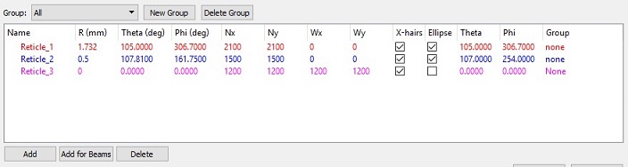
- The Reticles list display has been updated as follows:
- when adding or editing reticles, a separate Reticle Parameters dialog is no longer displayed. Reticle parameters are directly edited in the list boxes.
- displaying reticles as ellipses is now supported; while reticles sizes are entered as diameters, they appear in the X/Y views as elliptical because of the specified orientation angles (q,f) of the reticle's normal vector relative to the view.
- reticles are shown only for the Narrow View and Wide View cameras; the diameters are specified separately for the Narrow/X view (Nx), Narrow/Y view (Ny), Wide/X view (Wx), and Wide/Y view (Wy); if a diameter is zero, the reticle is not displayed.
- reticles can be associated with groups; the list of reticles shown contains reticles of the selected group; when adding a new reticle, it is automatically put into the group being displayed.
- the display of crosshairs is controlled individually for reticles.
- exporting reticle data to *.CSV files has been updated to include the additional reticle parameters.
- support for exporting reticle data to *.XML files has been added.
- the right-click menu is used to: set colors, show/hide reticles, move reticles from one group to another, and duplicate or delete reticles.
- Support has been added to generate "silhouette" images for the Narrow and Wide camera X-TVS and Y-YVS views. Characteristics of the silhouette images:
- the supported image format is PNG (Portable Network Graphics).
- images have a transparent background so that they can be overlaid on top of other images.
- reticles are not included in the images.
- exported images have extended areas such that 100 pixels on each side on the nominal camera views are added .
- users supply file base name and folder location for export; "-nx", "-ny", "-wx", and "-wy" are appended to the base file name ( "n", "w" for Narrow/Wide cameras; "x", "y" for X-TVS/Y-TVS views).
- For OMEGA and OMEGA-EP, reticles are no longer shown for the Standard, Smart Camera, and HS Video views.
- LMJ focal spot spatial profiles: For the "Elliptical Type A" profile, the radii were updated as requested.
- Surface of Revolution object: Updates were made to the user interface and documentation to clarify that when specifying a surface radius that is z-dependent, r(z), when computing r, the value of z is always assumed to be in units of cm.
- Picked Surface Nodes and Picked Surface Element Parameters utilities:
- Unit surface normal has been added.
- Values were made editable to facilitate Copy/Paste operations.
- Font colors were changed to improve readability.
- When selecting diagnostic ports, a check box is now included (at bottom right) to specify whether sub-ports at shown in the list.
- Chamber Components:
- Support has been added to automatically adjust position and orientation angle parameters when changing the Reference Coordinate System for a Chamber Component. To do this, check the "Automatically Update Position..." box at the bottom of the Chamber Component Parameters dialog.
- Chamber Components can now be copied to the Target Components List. Doing this allows these items to be included in laser deposition and radiosity calculations (i.e., it becomes possible to see if a chamber component is being hit by a laser beam). To do this, right-click on an item in the Chamber Components List, and select the Add to Target Components List menu item.
- When copying a Chamber Component, a new folder is created in the Target Components List, and the folder contains each of the objects used when the Chamber Component was originally created.
- When copying an object of a Chamber Component, the new Target Component is added to the top-level "Target Components" folder.
- The name of the new Target Components and folders in the Target Components List are adjusted if necessary to ensure that each name is unique.
- Users should ensure that materials properties, such as the albedo and x-ray conversion efficiency are set correctly for each of the newly created Target Components.
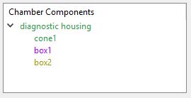
- Chamber Components List: Chamber Components are composed of one or more objects. For example, the can be created from one or more Target Components. The Chamber Components List now displays the objects that make up a given chamber component. This facilitates copying portions of a Chamber Component to the Target Components List.
- Creating Chamber Components from Target Components:
- A menu item has been added to support adding Target Components to the Chamber Components List. This option complements the capability to do the same action by dragging Target Components with the mouse down to the Chamber Components List. Using either of these methods, a new Chamber Component is created from one or more Target Components.
- The option to directly add Target Components to the Chamber Components Library has been removed. If one wants to do do this, Target Components can be added to the Chamber Components List, and then any Chamber Component can be added to the Chamber Components Library (use the Chamber | Open Components Library menu item).
- When running a simulation forward or backwards using the time selection controls (upper left of Main Window), a progress monitor is now displayed.
- Bug fixes:
- When editing a Memorized View, the Target Components box used when setting the scene position is now correctly loaded.
- When attaching one Target Component to another (using the Attach to Target Component menu item), the Reference Coordinate System is now correctly updated when the box requesting to do so is checked. Also, a check is performed on recursive referencing of coordinate systems.
- Problems occurring when selecting clusters in the Laser Beams List has been fixed (problems occurred Ver. 13.2.0 only).
- Problems occurring when importing STEP CAD files on Linux systems has been fixed (problems occurred Ver. 13.2.0 only).
| Copyright © 2000-2026
Prism Computational Sciences, Inc. |
VISRAD 21.1.1 |