
| CONTENTS | GLOSSARY | SUBJECT INDEX | SEARCH DOCUMENTATION |
On the OMEGA and OMEGA-EP laser systems, a 2ω or 4ω probe beam can be utilized. For OMEGA, the beam propagates along BL-25 and is intercepted by an HR pickoff and re-directed to Port P9. For OMEGA-EP, the probe beam is re-directed to Port 71.
Also on the OMEGA laser system, a 3ω probe beam can be utilized. The beam propagates along BL-35 and is intercepted by an HR pickoff and re-directed to Port P9.
In addition, a 3ω probe beam can be fed from OMEGA-EP which is directed to Port P9.
The probe beams can easily be added to the laser system by selecting the Lasers | Probe Beams | Add 2ω/4ω Beam (BL 25) or Add 3ω Beam (BL 35) or Add 3ω Beam (EP_TOP9) menu items. The beam is added as a Custom Laser Beam; therefore it can be deleted. Some of its properties, such as its name and f#, are not editable.
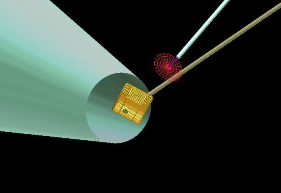
A Stay-Out Zone object can also be added to the target grid and displayed. This is a conical object, whose purpose is to evaluate whether Target Components are potentially interfering with the 2ω/4ω probe beam. To view the Stay-Out Zone, select the Lasers | Probe Beams | Add Stay-out Zone Object menu item. The object is added to the target component grid, and has many of the same features as a normal target component, with the exceptions that the name is not editable, and, by default, it is not included in laser deposition or radiosity calculations. The image below shows the Stay-Out Zone zone for the OMEGA chamber.
A reference to the Stay-Out Zone is also displayed below the 2ω/4ω Probe Beam in the Laser Beams List. The stay-out zone can be shown/hidden by right-clicking on the item. If selecting Show and the stay-out zone is not in the Target Components List, it is added to the list.
| Copyright © 2000-2026 Prism Computational Sciences, Inc. | VISRAD 21.1.1 |