
| CONTENTS | GLOSSARY | SUBJECT INDEX | SEARCH DOCUMENTATION |
To view the interior of a target system in the main graphics window, users can:
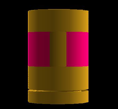
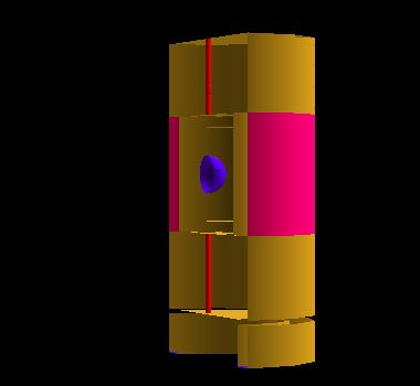
Examples images without (left) and with (right) cutaway clip planes applied is shown below.
Note that when cutaway clipping planes are applied to the display in the graphics window, they affect the graphics only. Calculated flux distributions and laser beams intersections continue to be computed for the whole grid.
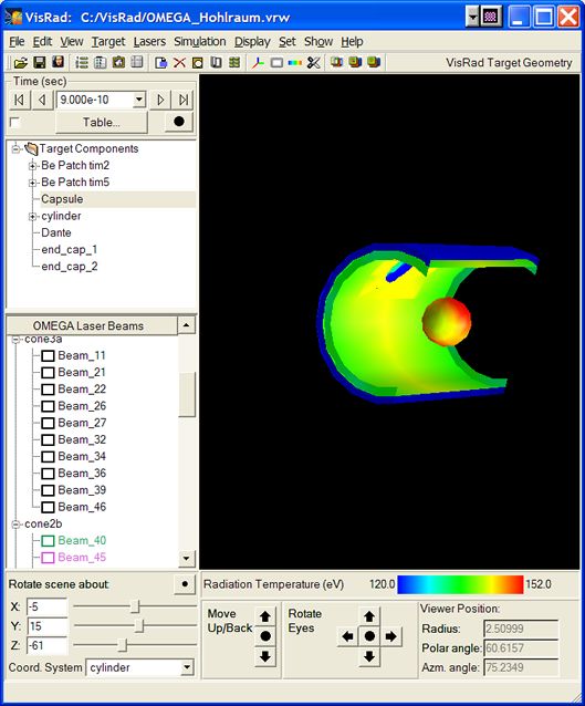
Cutaway views can also be applied when displaying results, such as the radiation temperature. An example image is below.
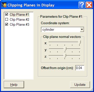
To set the clip planes used in the cutaway views, select Set | Clipping Planes, or click the Set Clip Planes button on the toolbar. Up to 3 clip planes can be applied. To activate a clip plane, check its box on the left.
Each clip plane can be applied in the target chamber coordinate system or in the coordinate system of any target component. The clip plane can then be rotated about the x-, y-, and/or z-axis. An offset of the clip plane to the origin of its coordinate system can also be applied.
| Copyright © 2000-2026 Prism Computational Sciences, Inc. | VISRAD 21.1.1 |