| CONTENTS | GLOSSARY | SUBJECT INDEX | SEARCH DOCUMENTATION |
The angular orientation of the object is specified by the Polar, Azimuthal, and Rotation angles.*
Each object type has a default orientation. For 2D objects (disks, rectangles, spokes), the object lies in the X-Y plane, with surface element normals pointing in the positive Z direction. Cylinders are symmetric about the Z-axis.
The orientation of an object, as well as its position, is determined using the Reference Coordinate System. The reference coordinate system can be the target chamber coordinate system, or any target component in the grid.
A transformation matrix is set up for each object, performing rotations and translations in the following order:
As an example, to point the symmetry axis of a cylindrical hohlraum at a port with polar and azimuthal angles given by θ and φ, just set Polar to θ and Azimuthal to φ. The cylinder can be rotated about its symmetry axis by adjusting Rotation.
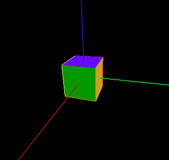
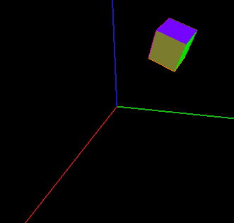
Example of transformation operations for a cube with:
| Position (cm) |
x = - 0.30
|
y = 0.10
|
z = 0.10
|
| Orientation Angles (degrees) |
Polar = 30
|
Azimuthal = 35
|
Rotation = 40
|
Initial Position:
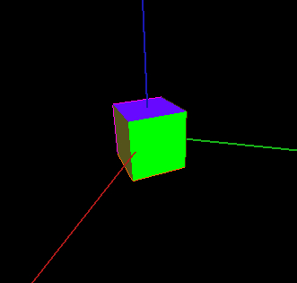
Rotation angle rotation (Step 1)
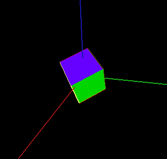
Polar angle rotation (Step 2)
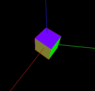
Azimuthal angle rotation (Step 3)
Position offset (Step 4)
_________________________________
* This method for specifying the orientation of target components was chosen over the pitch-roll-yaw method because it allows for conveniently orienting targets in chambers where port positions are given in a spherical polar coordinate system.
| Copyright © 2000-2026 Prism Computational Sciences, Inc. | VISRAD 21.1.1 |