
| CONTENTS | GLOSSARY | SUBJECT INDEX | SEARCH DOCUMENTATION |
1w (red cone) and 3w (blue cone) Reflection calculations (previously referred to as "Footprint" calculations) can be performed.
To generate a report, select the Lasers | Capture/Clearance Assessment, or click on the ![]() tool button.
tool button.
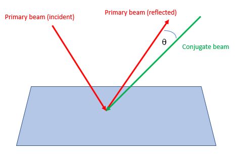
In 3w (1w) Reflection calculations, for all surface elements in the target mesh that see two or more blue (red) laser beams, the angles between the reflection of one of the beams (the "primary" beam) and the other beams (the "conjugate" beams) are computed (see sketch below). For each beam cone pair, the minimum of this angle (qmin) is computed for each surface element of a Target Component. The minimum value for each target component is reported in the Laser Beam Capture Clearance Report.
A 1ω (or 3w) laser beam cone is considered to hit a surface element of a Target Component if the element has a non-zero power computed for the cone.
When the 1ω (or 3w) Reflection calculation is completed, the minimum angle between each reflected beam and incident direction of conjugate beam is shown for each surface element in the Main Graphics Frame. (These results can also be displayed in the Main Graphics Frame using the Display | 1w (3w) Cone Overlap menu item.)
The Reflection calculations are performed for Target Components only (not Chamber Components).
The Reflection calculations are performed using enhanced beam radii parameters that are the same as those used for 3w (1w) Clearance calculations (specified in the Capture Clearance Setup Parameters widget). Note that user-specified defaults, set in the Config. Check tab in Preferences, can be readily utilized in performing laser beam capture/clearance calculations.
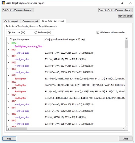
A table summarizing which target components see overlapping 1ω (3w) cones is shown on the Beam Reflection Report tab. The minimum angle between each reflected beam and incident direction of conjugate beam is shown for each Target Component.
Beams that have minimum angles less than the allowed tolerance (currently set at 5 degrees) are show in red.
Target component names are shown in the color as they appear in the Target Components List.
| Copyright © 2000-2026 Prism Computational Sciences, Inc. | VISRAD 21.1.1 |