

| CONTENTS | GLOSSARY | SUBJECT INDEX | SEARCH DOCUMENTATION |
Displaying transmission fractions is useful for checking surface-to-surface visibility; i.e., determining which surface elements in the target mesh are seen by a particular, or "picked", surface element.
When one surface element "sees" another surface element, the transmission fraction is 1. If is cannot be seen, the transmission fraction is 0.
Surface elements emit and absorb thermal radiation from only one side. Thus, surface elements have a preferred orientation. When the radiation flux throughout the grid is computed, the transmission fraction is defined such that the emitting/absorbing surfaces must see the sides of the surfaces doing the emitting/absorbing. To display surface-to-surface visibility relevant to the radiation flux calculation, select Display | Visible Surfaces (Rad. Flux); then double-click on a surface element in the grid to check which surfaces can be seen by the selected surface.
When computing the deposition and reflection of laser light, VISRAD allows either the "front" or "rear" side of a surface element to intercept the laser light. This laser light can then be reflected, and deposit the energy from the reflected light at other surface elements. To display surface-to-surface visibility relevant to the laser deposition calculation, select Display | Visible Surfaces (Laser Dep.); then double-click on a surface element in the grid to check which surfaces can be seen by the selected surface.
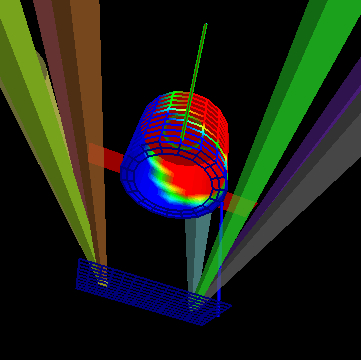
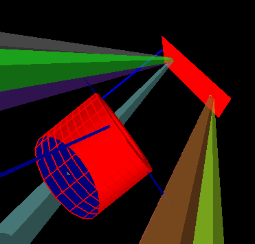
The images below show examples from a OMEGA halfraum target. Red indicates a transmission fraction of 1, meaning the picked surface element sees all other surface elements shown in red. Blue indicates a transmission fraction of 0, in which case the corresponding surface elements cannot be seen by the picked surface element.
In the left image, a surface element on the backlighter foil is selected with the mouse. This surface element is near the point where the backlighter beams on the left hit the foil, and is shaded in yellow. The surface elements in red see the picked surface element. That is, they directly see photons from the backlighter.
In the right image, a surface element at the bottom of the cylindrical halfraum is selected. (Again, it is small and has a yellow color.) This surface element sees the inside of the halfraum cylinder and the entire backlighter foil.


| Copyright © 2000-2025 Prism Computational Sciences, Inc. | VISRAD 21.0.0 |