
| CONTENTS | GLOSSARY | SUBJECT INDEX | SEARCH DOCUMENTATION |
Laser light energy is deposited in the hydrodynamics spatial grid using one of two models:
The Standard laser deposition model was originally developed for the deposition of optical laser light, and has the following features:
The model in which laser light is included as an External Radiation Source has the following features:
The Standard model is more suitable for optical lasers, while the External Radiation Source model is most often employed in simulations involving short-wavelength lasers. The External Radiation Source model is selected by checking the Include Laser Beam Radiation as External Source box in the Advanced sections.
In HELIOS, the laser source can originate from the inner or outer boundary of the hydro grid -- i.e., R(min) or R(max) -- or at the boundary between any two spatial Regions.
For a source originating at an interface between two regions, the region name and the side at which the source originates must be specified. For example, to set up a laser source originating on the R(max) side of region "Plastic_1", select Plastic_1 for the name and R(max) for the boundary. Laser sources originating on a boundary on the R(max) side of a region propagate in the direction of R(min).
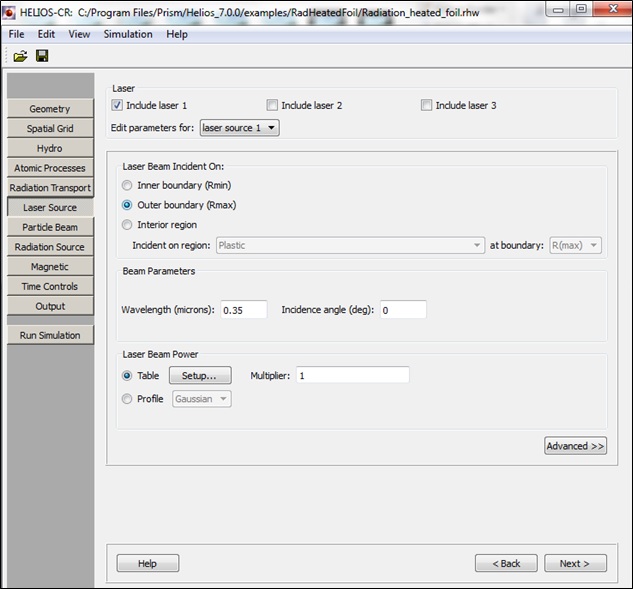
The time-dependence of the laser beam power can be entered into a two-column table of times and beam powers, or a Gaussian profile can be chosen.

Note that in planar geometry the laser powers are entered as TW/cm2, while for spherical geometry and cylindrical geometry the power is in units of TW and TW/cm, respectively.
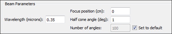
Beam Parameters
The Beam Parameters section is used to specify:
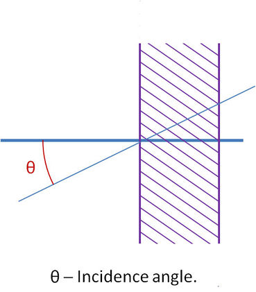
For planar geometry, the Incidence Angle is entered (see top image on this page). For cylindrical and spherical geometries, the focal position, the half cone angle, and the number of angles is specified (the default for the number of angles is the number of zones in the plasma).
Additional Laser Source modeling options can be viewed by clicking on the Advanced button. Modeling options include:
The above options can be specified on a beam-by-beam basis in a multiple beam simulation.
When the Standard laser deposition model is employed, the following options are also available:
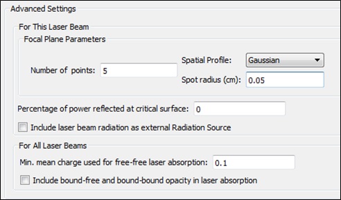
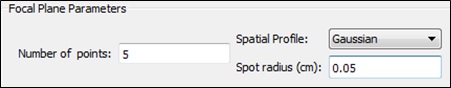
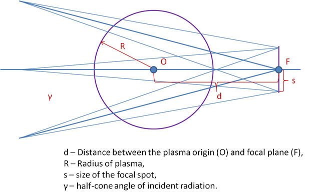
For cylindrical and spherical geometries, additional focal plane parameters, discussed below in Ray-Trace Modeling description, can be entered on the Advanced section:
The direction of laser ray propagation across the zone boundaries inside the plasma is governed by Snell's law, where the refractive index is determined by the local values of electron density. At the zone there the critical value of the electron density is reached (critical surface), a user-specified fraction of laser energy can be reflected back into the plasma. Any energy remaining in the beam is deposited. In this model, laser energy is not allowed to penetrate beyond the critical surface.
For planar geometry, the laser beam is assumed to propagate along a single ray. The angle between this ray and the normal to the zone boundaries is given by the Incidence angle.
For spherical or cylindrical geometry, a more elaborate ray tracing algorithm is utilized. This allows for a more realistic calculation of the laser energy deposited within the 1-D modeling. The following parameters define the modeling geometry:
The default number of angles within a cone is equal to the number of zones in the problem. The number of rays for the focal spot is 1 (basically, it assumes that the laser focuses to a point). For non-zero spot size, where the number of rays for the focal spot is greater than one, the angles of incidence for each ray are recomputed. The point of origin for each ray is assumed to be sufficiently far from the plasma that the rays entering the focal plane can be treated as parallel.
The spatial profile of the laser intensity at the focal spot in spherical and cylindrical simulations can be specified to be either uniform or Gaussian. For Gaussian profile, the spot size determines the location where the laser intensity is decreased by a factor of 1/e.
| Copyright © 2002-2025 Prism Computational Sciences, Inc. | HELIOS 11.0.0 |