
| CONTENTS | GLOSSARY | SUBJECT INDEX | SEARCH DOCUMENTATION |
In addition to using the Graphics Viewing Controls and Engineering View Buttons to change the display orientation, the exact position of the Viewer and Scene can be specified by selecting Set | Viewing Position menu item.
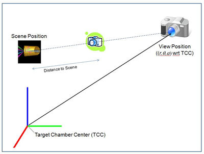
The Scene location is the point which is being looked at, while the Viewing location is the position at which the viewer's eyes are located. This is shown schematically in the illustration below.
Two options are available for setting the view:
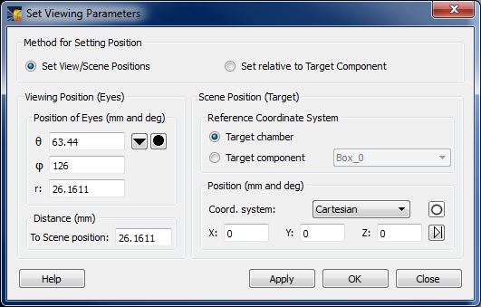
Setting Specific Coordinates for the View and Scene PositionsFor this option, select the Set View/Scene Positions button.
In this case, a spherical polar coordinate system is used to define the View position (r,θ,φ). For convenience, the polar and azimuthal angles of each of the diagnostic ports are provided (accessed using the (
) button in the Viewing Position box), as well as those for the laser beam ports (accessed using the (
) button). For laser systems having Target Positioning Viewers, the angles associated with available camera views are also available.
The value r for the Position of Eyes is the radius in the Target Chamber spherical polar coordinate system. By contrast, the Distance to Scene Position is the distance from the Scene position along a line to the Position of Eyes, or Viewing position (see illustration above).
The Scene position can be specified using the Target Chamber coordinate system, or the coordinate system of any target component.
For convenience, the position of various Key Points of target components (e.g., the top or bottom of a Cylinder, or the corner of a Box) can be entered using the (
) button in the Scene Position box. To use this approach, click on the button, and select a Target Component with the mouse in the Main Graphics Window. This will highlight the Key Points of the picked component, and pop up the Target Component Positions dialog with the positions of the Key Points highlighted in the table. Double-click on one of the Key Points of the points in the table, and that point's position will automatically be entered as the Scene position in the Set Viewing Parameters dialog.
Note that the scene can be centered on a Target Component by picking the component in the Main Graphics Frame, and pressing 'c' on the keyboard.
The (
) button is used to reset the Scene position to (0,0,0).
The rotation of the 'Up' vector with respect to the target chamber z-axis can also be edited.
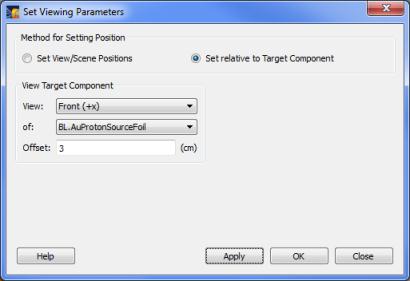
Setting the Viewing Position Relative to a Target Component
For this option, select the Set Relative to Target Component button.
In this case, the View position is set with respect to the specified Target Component (or the Target Chamber Center). The Scene position is set to that of the target component being viewed.
The Offset is the distance (in cm) from the Scene position to the View position.
The View position is displace from the Scene position using the coordinate system of the Target Component. Options for the orientation of the View relative to the Scene are:
- Front (displaced in + direction along the x-axis)
- Back (displaced in - direction along the x-axis)
- Right (displaced in + direction along the y-axis)
- Left (displaced in - direction along the y-axis)
- Top (displaced in + direction along the z-axis)
- Bottom (displaced in - direction along the z-axis)
An option is also provided to display an Isometric view, where the View is displace equally along the component's x-, y-, and z-axes.
When changing to the new viewing position, the display migrates through a series of views along the way to the final position. This provides a sense of movement through the chamber. This animation effect can be turned off, or its parameters can be adjusted, by editing the Change View Position parameters on the Graphics tab of the Preferences dialog.
Setting to the Home Viewing Position
When setting to the "Home" viewing position using the Set Home View toolbar button (![]() ), the scene position is set to target chamber center [S = (0,0,0)], the eye position is set to E = (20,20,20) mm.
), the scene position is set to target chamber center [S = (0,0,0)], the eye position is set to E = (20,20,20) mm.
| Copyright © 2000-2026 Prism Computational Sciences, Inc. | VISRAD 21.1.1 |