Fixed problem reading in OMEGA probe beam angles from non-JSON workspace files.
Fixed problem reading in MEC beam angles from JSON workspace files.
Fixed problem reading in NIF ARC beams parameters from JSON workspace file.
Version 21.1.0
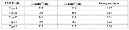
LMJ Phase Plate parameters were updated as follows:
Phase Plate settings: When reading in laser beam spatial profile parameters from a VISRAD workspace file, a check is made to see if the spatial profile parameters (Rmax, Rmin, supergaussian exponent, spot size definition model) are consistent with the default parameters for the phase plate being used. If inconsistencies are found, a warning is shown and the user is prompted to choose between staying with the workspace values or the default phase plate values. This warning can be turned off in Preferences.
When setting the viewing position (Set | Viewing Position menu item), checks are made to make sure the Eye and Scene positions are not identical.
Laser-Target Capture Clearance Report: Data from the Capture Report tab (capture fraction and max. incident angle) can now be exported to an ascii text file by clicking on the Export Data button. Data is exported as it is shown in the table.
In JSON-formatted workspace files, the text string "Beam cone F numuber" was replaced by "Beam cone F number". VISRAD will accept either of these as the key word for that parameter.
Updated progress bar for radiation flux calculations to better reflect simulation progress.
This version is built with updated libraries for STEP file reader.
Updated dynamic libraries for software activation.
Mac distributions are now built on ARM processors and are digitally signed. This should reduce issues with MacOS quarantining and blocking the application. Supported OS: Sonoma (14.8) or newer.
Bug fixes:
In the target positioning views, the z-position of the reticle cross hairs in the viewing plane was adjusted so that they appear in front of the target.
When using non-zero wall thickness and centering the wall at the specified object position (option only for Disks, Rectangles, and Spoked Disks), the object Key Points shown in the Main Window and listed in the Target Component Positions dialog are now corrected for the centering.
Spoked Disks: Keys Points have been added (affects viewing in the Main Window and the Target Component Positions dialog).
Bug fixed that resulted in "nan" values for viewing vectors (eye, scene, and up vectors) has been fixed.
MEC Laser System: beam parameters for modified port angles and F numbers are now stored and read in correctly from the workspace file. Only the X-ray beam remains fixed.
Fixed progress bar for laser beam calculation when performing multi-threaded simulations.
Fixed problem with Sinusoidal projection when viewing surface element contour plots.
Version 21.0.0
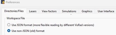
Support for utilizing JSON-formatted workspaces has been added.
This option provides better support for reading/writing workspaces that use different versions of VISRAD.
JSON-formatted files can be readily modified using scripting tools such as Python.
To turn this option off, check the "Use non-JSON format" button on the Directories/Files tab of Preferences. By default, this option is now turned on.
When saving a workspace that was originally read in using the old (non-JSON) format, a warning is presented notifying the user that it is now being saved to a JSON-formatted file. (This warning can be turned on/off in the Warnings tab of Preferences.)
The OpenGL graphics in each of VISRAD graphics widgets has been updated to utilize virtual buffer objects. This was done in order for VISRAD to work effectively on more modern computer monitors and graphics acceleration hardware.
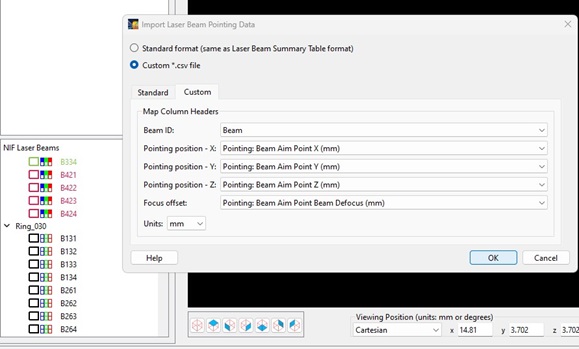
Updates were made to facilitate importing pointing data from NIF SST files. When importing data:
the widget that pops up has the columns set as shown in the image below
the reference coordinate system for the beam pointing is set to "Target Chamber"
the beam power is turned on or off based on whether pointing data exists for that beam
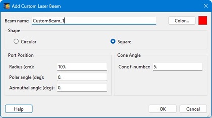
Custom Laser Beams: The ability to add square custom laser beams has been added. Previously, custom beams were assumed to be circular. When adding a custom beam, select either Circular or Square. Once added, the shape cannot be changed.
For the 2-D target components Disk, Rectangle, and Spoked Disk, when using a Non-Zero WallThickness, an option to place the center of the wall at the location specified in the Object Position Parameters tab has been added. To utilize this, check the 'Place center of wall using object position params' check box on the Size/Gridding tab.
If this box is not checked, the primary wall of the 2-D component is placed at the location specified in the Object Position Parameters tab, and the opposing wall will be place using an offset defined by the Wall Thickness.
The VISRAD documentation has been updated to better describe the effects of a Non-Zero WallThickness on the grid.
Note that for Sphere, Cylinder, Cone, Box, Torus, Cylindrical Hohlraum, Cylindrical Halfraum, and Rugby Hohlraum objects, the grid dimensions (size) define the outer wall(s) of the object. The inner wall(s) are located inward by an amount specified by the Wall Thickness.
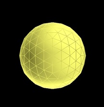
A Geodesic Sphere has been added an an option for a Target Component. This object has triangular surfaces elements that are more similar in area near the poles and equator, and therefore may be more suitable to use in radiosity calculations than the normal Sphere object.
A button to reset viewing parameters to their default values has been added to the Main Window toolbar. When the Set Home View button () is pressed, the Scene position is set to target chamber center, and the Eye position is set to its default value.
The Target Assembly Viewer is now available to all users when the target chamber is either OMEGA or OMEGA EP. This shows viewing angles and measurements specifically requested by the target fabrication team at the University of Rochester..
The use of "Transparency" for Laser Beams has been updated to be consistent with the use of the same term for Target Components. A value of 1.0 now means fully transparent, and 0.0 means opaque. The default value remains at 0.5.
The color bar overlay in the Main Window is now hidden whenever the display is reset to showing the grid (Display | Grid menu item).
Bug fixes:
Bug that occurred for the measuring tool and grid lines in the Main Graphics Frame has been fixed. This bug occurred only in ver. 20.0.0.
Fixed problem with generating grids for a Cylinders with non-zero wall thickness, where some inner polygons were missing. The changes have a minimal effect on computer laser deposition or radiosities in cases where the wall thicknesses were small (compared to the cylinder radius). The missing polygons size was equal to the wall thickness. In cases that use a large wall thickness, the effect is more noticeable.
When editing the Size/Grid parameters for multiple Target Components, if the surface normals parameter is not the same for all components, both buttons are set to be unchecked, and therefore the normals parameter will not be changed unless one of the buttons is selected.
Version 20.0.0
The way in which the graphics are rendered in the Main Window has been modified. The purpose is to make manipulating the view easier and more intuitive. Note that the updated link for the Help button (, lower right of Main Window) now goes directly to the help page on Graphics Viewing Controls.
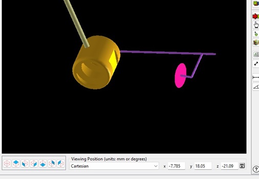
The viewing position ("eye" position) is now tracked and can be displayed at the bottom of the Main Window (see lower right in image below).
Toggling between showing the Viewing Position values and the Color Bar Panel (shown in previous versions of VISRAD) is controlled by right-clicking on that area of the Main Window.
When displaying data (using the Display menu), the Color Bar Panel is automatically displayed for all quantities other than Grid (in which case the Viewing Position values are shown).
Picking on items in the Main Graphics Frame:
To select a Target Component, pick with mouse.
Double-click to show its properties dialog.
Engineering Views are updated to be based on the picked component.
If coordinate system axes are displayed (using Show | Axes menu item or toolbutton), the axes are updated to be those of the picked component.
To select a Surface Element, use SHIFT + pick with mouse.
SHIFT + double-click shows the surface element's node positions dialog.
The selected beam in the Laser Beams List is set to the picked beam.
Because of the modified rendering, several options have changed:
The "Orbit About Picked Surface/Object" toolbutton () has be eliminated. Instead rotations are performed around a picked Target Component, Surface Element, or target chamber center using the 'Rotation' toolbutton (see below).
The "Adjust View Angles" toolbutton () has been replaced by an "Adjust Up Vector" toolbutton () that allows the view in the Main Graphics Frame to be rotated.
The rotation of the 'Up' vector, which represents the rotation of the view with respect to the target chamber z-axis, is now shown in the Set Viewing Parameters dialog.
The option to show the Main Graphics Frame using Perspective projection has been removed. Orthographic projection is now always used.
The option to show the Scene Rotation Controls in the lower left panel of the Main Window has been removed. (This panel was only shown if it was set in Preferences). Its capabilities are also available using the 'Rotate About Surface' () toolbutton.
Shortcuts have been added for manipulating the graphics in the Main Window.
Pressing the space bar: Puts the viewing back to pointer mode (same as clicking on ).
Pressing "r" changes cursor to Rotation mode (same is clicking on ).
if a Target Component has been picked with the mouse, the rotation about that object.
if a Surface Element has been picked with the mouse (picking while holding the SHIFT key), the rotation is about that surface element.
if neither of the above is picked, the rotation is about target chamber center (TCC),.
Pressing "c" after a Target Component has been picked with the mouse: The view is translated so that the picked item is centered in the view.
Pressing "z" changes cursor to Zoom mode (same as clicking on ).
Pressing "t" changes cursor to Translate mode (same as clicking on ).
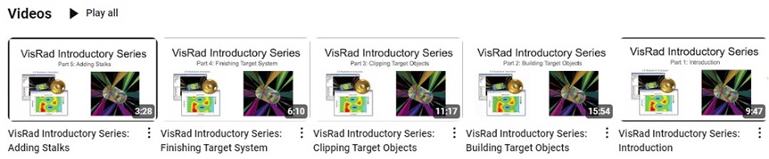
A series of introductory videos on using VISRAD is now available (see https://www.youtube.com/@PrismCS-m2w). This initial set of videos focuses on setting up Target Components. They can be acessed using the Help | Tutorials menu item.
Workspace Increments can now be saved. An "Increment" is a temporary file that is written to a folder that stores the workspace parameters without overwriting the current workspace. Users can choose to go back and reload a workspace increment by simply browsing for the file.
To save a workspace increment, use either the File | Save Increment menu item, or click on the tool button.
The folder used for storing increments has the same name as the current workspace file, but without the ".vrw" extension.
The name of the increment is the same as the workspace file with an integer appended to the name.
When closing the workspace, the user is prompted to save or delete the folder containing the workspace increments.
Main Window Graphics Frame background color: If a background color for viewing is set to be used in Preferences (Graphics tab), the specified background color will be used when loading in a new workspace file. To use the color saved in the workspace file, select Use Default Color in the Background Color (Viewing) box.
NIF Laser System: Added support for exporting laser beam data suitable for the NIF SST. To do this, select the File | Export Laser Beam Data | NIF SST Beam Data menu item. The data is written to a '.csv '-formatted file suitable for reading into Excel.
OMEGA Laser System: A new DPP was added to the list of available phase plates ("OMEGA 100 um (SSD off, DPR out) DPP").
Line-Target Intersection Points Tool: The line is now shown when the Update button is pressed, and shown as long as the Line-Target Intersection Points Tool is open.
Orientation Angles Calculator: The distance between the two points used to compute orientation angles is now also shown.
When showing the line-of-sight for a Diagnostic Port (using Show LOS column in the Port Positions Dialog), the line-of-sight now extends beyond the target chamber origin. It is shown as a dashed line in the direction away from the port.
When adding a Stalk object using the Picked Surface Node Positions () tool, the default for the surface normals is set to "out".
Movie Creator:
Support for directly generating a single video (*.avi) file has been added. AVI files can be viewed by a variety of movie players.
When adding a Movie View to the list of views, the viewing parameters now default to those currently in use in the Main Graphics Frame.
Double-clicking on a view in the Movie Views list displays that view in the Main Graphics Frame.
Bug fixes:
Fixed crash when attempting to attach multiple target component Stalks to a single Target Mount.
Fixed crash that occurred in some cases after deleting a Clipping Volume.
Clipping Volume Parameters dialog: fixed bug for automatically adjusting position values when changing the Coord. System in the Position box.