
Sample Problem: Cylindrical Hohlraum at OMEGA
Setting Up the Grid
This sample problem includes several features and tools in VISRAD designed to facilitate target grid setup:
In this example, we set up a hohlraum for the OMEGA target chamber with the following characteristics:
- The hohlraum is aligned along the P6-P7 axis
- The hohlraum cylinder is mounted to a stalk originating from TIM #3
- A flat region is cut into the side of the hohlraum
- A backlighter is located above the flat region on the side opposite from TIM #5 (Port H14)
- A hole is cut into the hohlraum to provide a line-of-sight that passes through TIM #5, the flat region, and the center of the backlighter.
- The hohlraum wall is viewed through one of the LEHs with Dante.
Step-by-step instructions for setting up a hohlraum target are:
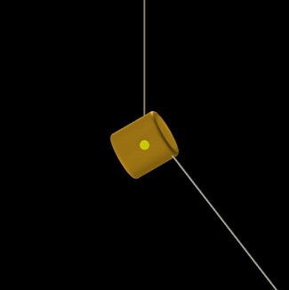
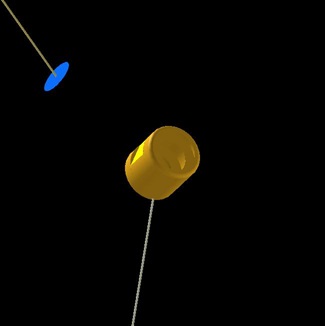
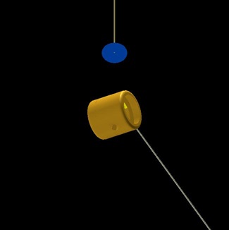
The images below shows the target after all of the steps is completed. The views are set using the Set Viewing Position dialog. Left: TIM #5 view (Port H14). Center: Dante view (Port H16-I) . Right: X-TVS view.
Cylindrical Hohlraum Setup
The hohlraum cylinder will serve as the reference coordinate system for several other target components. Doing this, all of the components will stay attached to the hohlraum if its Position or Orientation Angles change.
- Open the Port Positions Dialog. Check the Show LOS box for P6 to view the port line-of-sight (LOS).
- Add a Cylindrical Hohlraum object
aligned along the the P6-P7 axis:
- Set the name to "hohlraum".
- In the Position tab:
- Set the Reference Coordinate System to the P6 Port Axis.
- In the Size/Gridding tab:
- Set the Radius to 0.8 mm, the Length to 1.6 mm
- Set the LEH Radius to 0.6 mm, and R-Corner to 0.1 mm.1
- Set the number of grid points to 21 along the z-axis, 24 in the azimuthal direction, and 4 for the Radial (end disks).
- For hohlraum objects, the Surface Normals are automatically set to In.2
Insert Shields Inside the Hohlraum
Add open shields on the inside of the hohlraum at the edges of where the flat sample will be located.
- Add a Disk object and set the name to "inner_shield_1".
- In the Position tab:
- Set the Reference Coordinate System to that of the Target Component "hohlraum".
- Set z = 0.4 mm.
- In the Size/Gridding tab:
- Set the Outer Radius = 0.8 mm, Inner Radius = 0.5 mm.
- Set the number of grid points to 6 in the radial and 24 in the azimuthal dimensions.
- User a non-zero wall thickness of 0.01 mm.2
- Add a second shield by duplicating "inner_shield_1".
- Right-click on "inner_shield_top" in the Target Components List and select Duplicate. A new object called "inner_shield_1_2" appears in the list. Edit this object.
- Set the name to "inner_shield_2".
- In the Position tab:
Backlighter Setup
Place a 0.5 mm radius disk backlighter a distance 4 mm from target chamber center (TCC) in the direction away from H14.
- Check the Show LOS box for H14 in the Port Positions Dialog to view the port line-of-sight (LOS).
- Add a Disk object for the backlighter.
- Set the name to "backlighter".
- In the Position tab:
- Set the Reference Coordinate System to that of the Port Axis H14 (the coordinate system for a port has its origin at TCC and its z-axis is along its LOS)
- Set z to -4 mm.
- In the Size/Gridding tab:
- Set the Outer Radius to 0.4 mm.
- Set the number of grid points 24 for the azimuthal direction
- Set the Surface Normals to Down.
Cut a Diagnostic Hole in the Hohlraum Along the Line from H14 to the Center of the Backlighter
Clip the "hohlraum" such that there is a clear line-of-sight that extends from H14 (TIM #5) (i.e., a point located, say, 30 cm from TCC in the direction of H14) to the center of the "backlighter".
- Right-click on the "hohlraum" in the Target Components List, and select Clip.
- Select a Cylinder clipping volume.
- Use the Line-Target Intersection Points Tool to find the point on the cylindrical hohlraum that is intersected by the H14 / Backlighter line.
- In the tool, for the Start point, select Port Axis "H14", and set z = 300 mm.
- For the End point, select Target Component "backlighter", and use the origin (x = y = z = 0).
- Press the Update button to generate a list of the intersection points (positions are given in the Target Chamber coordinate system).
- Select the "hohlraum" intersection point that lies furthest from the "backlighter", and press the Coordinate Transform (
 ) button, to bring up the Coordinate Transformation Tool with the "hohlraum" intersection point pre-loaded for the Base point position.
- In the Coordinate Transformation Tool, for the Reference Coordinate System of the New point, select the Target Component "hohlraum" and select Cylindrical geometry.
- Pressing the Update button gives the intersection point position in the coordinate system of the "hohlraum" (It is r = 0.0796 cm, z = 0.0152 cm, φ = 288.0 deg).
- Right-click on one of the position boxes (either r, z, or φ), and select Copy Position Variables.
- In the Clipping Parameters Dialog:
- In the Position tab:
- Use the "hohlraum" as the Reference Coordinate System, and use a Cylindrical geometry.
- Right-click on one of the position boxes (either r, z, or φ), and select Paste Position Variables.
- For the Orientation Angles, enter θ = 90 and φ = 288.0 degrees (this sets the clipping volume to be orthogonal to the side of the hohlraum).
- In the Size tab:
- Set the Radius to 0.15 mm, the Length to 1 mm and Number of Grid Points to 24 (the length only needs to be a value that will cut through one side of the hohlraum).
- Select Show | Clipping Volumes menu item to view the cylindrical clipping volume.
Add a Flat Rectangular Surface on the Side of the Hohlraum
Add a flat rectangular surface (of length 800 μm) on the side of the hohlraum, and position it such it is along the line of sight from the H7-H14 (TIM #5) axis. Put the flat on the H7 side.
- Clip the hohlraum at its middle (z = 0) and φport = φport.
- Right-click on "hohlraum" in the Target Components List and select Clip. Select a Box clipping volume.
- In the clipping volume Positions tab, use the "hohlraum" as the Reference Coordinate System.
- Set the Coordinate System to Cylindrical, and set r = 0.9 mm,3 z = 0, and φ = 108 deg (180 degrees away from the diagnostic hole).
- Set Polar angle = 0, Azimuthal angle = 108 (= φport).
- Hit the Apply button, and display the clipping volume (menu item Show | Clipping Volumes).
- In the Size tab, set x = 0.4 mm, y = 2 mm, z = 0.8 mm.
- Add a Rectangle where the surface has been removed.
- Set the name to "flat", and change the color to readily distinguish it from the hohlraum.
- In the Position tab:
- Uncheck the box at the bottom ("Automatically update...")
- Set the Reference Coordinate System to that of the Target Component "hohlraum".
- Set the Coordinate System to Cylindrical.
- Set r = 0.7 mm, z = 0, and φ = 108 (= φport).
- Set Polar angle = 90, Azimuthal angle = 108 (= φport).4
- In the Size/Gridding tab:
- Set x = 0.8 mm and y = 0.7746 mm.5
- Set the Surface Normals to Down.2
Attach the Hohlraum to the TIM #3 (H18) Target Mount
Add a 0.03 mm radius stalk to the "hohlraum".
- Check the Show LOS box for H18 in the Port Positions Dialog to view the port line-of-sight (LOS). The solid portion of the LOS faces H18. We can attach a stalk to any hohlraum surface element on that side of the hohlraum.
- Pick on a surface element using the Picked Surface Node Positions (
 ) tool.
- Select the surface element centroid or one of the node positions, and click on the Add a Stalk at Selected Node button.
- Set the stalk name to "stalk_hohlraum".
- Click OK, and a message is presented indicating the the referenced coordinate system for the "hohlraum" has been changed to target mount TM-TIM3 (previously its reference coordinate system was "Target Chamber").
Attach the Backlighter to Stalk from TPS #2
Add a 0.03 mm radius stalk to the "backlighter".
- View the back of the backlighter by first picking on it, and using the Engineering Views button corresponding the the bottom view.
- Pick on a surface element near the center of the backlighter using the Picked Surface Node Positions () tool.
- Select the surface element near the center of the backlighter, and click on the Add a Stalk at Selected Node button.
- Set the stalk name to "stalk_backlighter".
- Click OK, and a message is presented indicating the the referenced coordinate system for the "hohlraum" has been changed to target mount TM-TIM3 (previously its reference coordinate system was "H14").
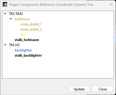
The Target Components Reference Coordiate Systems Tree is useful in seeing how various Target Components are referenced to each other. It can be viewed using the Target | Show Ref. Coord. System Tree menu item.
_________________________________________
1 Setting R-Corner to 0.01 cm provides a rounded edge to the cylinder.
2 It is important to set the surface normals appropriately for radiation calculations. Surfaces have a preferred
orientation, emitting/reflecting light on one side only. To emit/reflect light on both sides, either an object with non-zero thickness must be used (see Size/Grid tab of Object Parameters Dialog), or a second, nearly identical object must be set up which has surface normals facing in the opposite direction.
3 This is the centroid position of the clipping volume box. Since we will use a clipping box with a height of 0.4 mm and place the flat (rectangle) a r = 0.7 mm, the centroid of the clipping box is at r = 0.7 + 0.5*0.4 = 0.9 mm.
4 For information on setting the Polar and Azimuthal values, see Specifying Orientation Angles.
5 The value of 0.07746 = 2*sqrt( Rhohlraum 2 - Rflat 2) = 2*sqrt( 0.082 - 0.072).
| Copyright © 2000-2026
Prism Computational Sciences, Inc. |
VISRAD 21.1.1 |