
| CONTENTS | GLOSSARY | SUBJECT INDEX | SEARCH DOCUMENTATION |
Parameters on the Position tab are used to specify the position and (angular) orientation of the object.
An object's position and orientation can be specified in:
For some target chambers, when the Target Chamber button is selected, it is also possible to select one of the Target Mounts (e.g., TM-TIM1 for OMEGA) as a reference coordinate system. When a target component is attached to a Target Mount, it can be manipulated in the Target Positioning Viewer.
A Cylinder or Cone target component can be designated to be a Stalk object by setting its Designation in the Object Parameters Dialog, and using a Target Mount as its Reference Coordinate System. Stalk objects are used to map the position of a target component set up in the Main Graphics Window to the Target Positioner Rotation/Translation controls used in the Target Positioning Viewer. (See Designating Target Components as Stalks for more details.)
An example of building a target mounted to an OMEGA Target Mount is shown in the OMEGA Cylindrical Hohlraum example.
In the case of using a diagnostic port as the reference coordinate system, the origin is at target chamber center, and the z-axis points at the diagnostic port. The x-axis points in the positive θ direction, where θ is the target chamber polar angle.
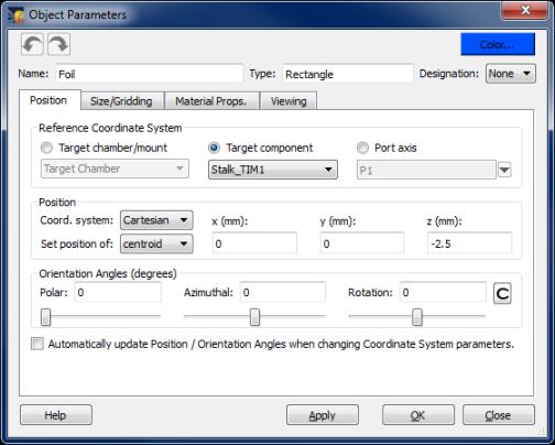
When changing the Reference Coordinate System for an object, it is possible to have the Position and Orientation Angles automatically re-computed. To do this, check the box at the bottom of the Position tab prior to changing the Reference Coordinate System. The new values are then automatically entered in the boxes when the coordinate system is changed.
When changing the Coordinate System in the Position box (e.g., from Cartesian to Spherical), the position values are automatically updated such that the position vector is maintained even if the "Automatically Update Position" option is not checked. This feature can be turned off in the User Interface tab of the Preferences dialog.
It is possible to reset the Reference Coordinate System for one or more Target Components to one of the Target Mounts by selecting the objects in the Target Components List, and then selecting the right-click menu item Attach to Target Mount.
Position values are typically entered in units of cm (or degrees in the case of angles). To change the default units used to specify position, go to the User Interface tab of the Preferences dialog.
The position of the object can be specified by the position of its centroid. For several objects, it is also possible to specify the position of other key points.
"Corner" points are identified by the octant or quadrant at which they appear when the centroid is at the origin. For example, "Corner +++" refers to the point of the box that is in the +x, +y, +z octant.
In the Position box, the user specifies the position of the object. This can be done in Cartesian, cylindrical, or spherical coordinate system geometries.
In the Orientation Angles box, the user can specify the orientation of the object. This is done using 3 angles: "polar", "azimuthal", and "rotation". These angles can either be entered in the boxes adjacent to the angle labels, or by adjusting the sliders located below the boxes. As the sliders are adjusted, the Main Graphics Frame is automatically updated. See Specifying Orientation Angles for definitions, and details on setting these angles.
| Copyright © 2000-2026 Prism Computational Sciences, Inc. | VISRAD 21.1.1 |